This is my second Amp Camp build. Like my first one, this will be a drawn-out affair. However, I’ve got it pretty well planned out and I’ve already made some progress in construction.
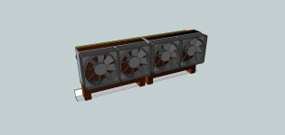
My primary motivation for this build was a pair of fan-cooled copper heat sinks I found at the local electronic salvage store a few months ago, which cost me $9 each. I knew I had to figure out some way to put them to good use. The fans are pretty quiet at low speeds, and I figured they would be good for a small ACA build… so here we are.
Unlike my last build, this time I’m going to alter the circuit a little bit based on a suggestion made by Zen Mod in the official Amp Camp thread. I’ll be switching out the IRFP240 mosfets with IRFP150s, “crank[ing] up the voltage,” and halving the values of R1 - R4. That should produce an “ACA on steroids” according to Zen Mod. We’ll see how that works out. If it doesn’t, it’ll be easy enough to swap in the standard components. My plans for this amp are to use it to drive moderately-sized subwoofers, using my current ACA mono blocks to drive a couple of small two-ways.
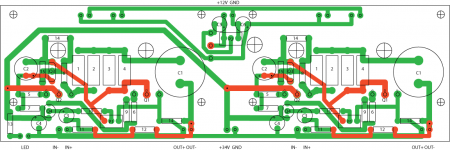
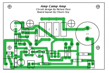
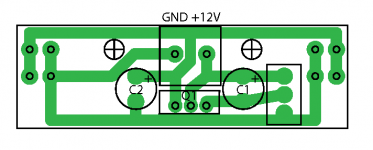
In order to fit my case design and to keep everything neat & tidy, I’ll be making my own 2-sided PCBs, something I’ve never done before. I laid out the board using Adobe Illustrator:

You’ll note I’ve included circuitry for a mosfet-base fan controller. I’m not 100% sure I’ll be using that circuit, so that part of the board may change.
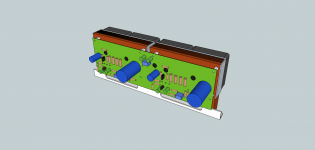
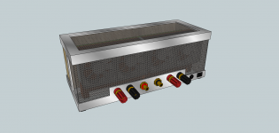
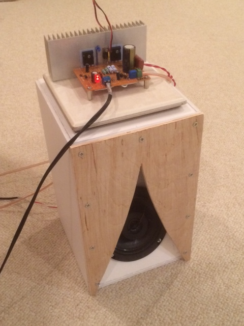
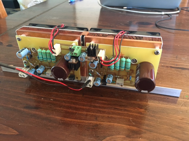
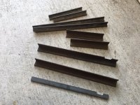
The heat sinks (with fans) will be connected with a piece of aluminum angle, and the PCB will mount to the heat sinks. Aside from the power jack, switches, LED, and in/out connectors, all the working parts of the amp will be included in this assembly:


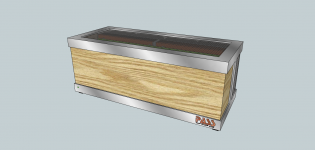
The case framework will be made of welded steel. Wood at the front and perforated steel at the top and rear will complete the case:


In addition to the usual metal work and wood work, there’ll be some other fun stuff like etching and plating, so hopefully some of you will find this interesting. Stay tuned…
😀
Edit: If you have Sketchup (and I suggest you download it if you don't), you can download my model here:ACA Concept to .skp model (zipped).
My primary motivation for this build was a pair of fan-cooled copper heat sinks I found at the local electronic salvage store a few months ago, which cost me $9 each. I knew I had to figure out some way to put them to good use. The fans are pretty quiet at low speeds, and I figured they would be good for a small ACA build… so here we are.
Unlike my last build, this time I’m going to alter the circuit a little bit based on a suggestion made by Zen Mod in the official Amp Camp thread. I’ll be switching out the IRFP240 mosfets with IRFP150s, “crank[ing] up the voltage,” and halving the values of R1 - R4. That should produce an “ACA on steroids” according to Zen Mod. We’ll see how that works out. If it doesn’t, it’ll be easy enough to swap in the standard components. My plans for this amp are to use it to drive moderately-sized subwoofers, using my current ACA mono blocks to drive a couple of small two-ways.
In order to fit my case design and to keep everything neat & tidy, I’ll be making my own 2-sided PCBs, something I’ve never done before. I laid out the board using Adobe Illustrator:
You’ll note I’ve included circuitry for a mosfet-base fan controller. I’m not 100% sure I’ll be using that circuit, so that part of the board may change.
The heat sinks (with fans) will be connected with a piece of aluminum angle, and the PCB will mount to the heat sinks. Aside from the power jack, switches, LED, and in/out connectors, all the working parts of the amp will be included in this assembly:
The case framework will be made of welded steel. Wood at the front and perforated steel at the top and rear will complete the case:
In addition to the usual metal work and wood work, there’ll be some other fun stuff like etching and plating, so hopefully some of you will find this interesting. Stay tuned…
😀
Edit: If you have Sketchup (and I suggest you download it if you don't), you can download my model here:ACA Concept to .skp model (zipped).
Attachments
Last edited:

With fan cooling you will want air filters before things get too gross.
Good idea, Thanks.
naah , with lazy flow - that's not pro amp with full blasting vents
blasting with some compressed air , once or twice per year , is enough
blasting with some compressed air , once or twice per year , is enough
Construction begins...
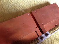
Drilling the holes in the mounting bracket and heat sinks:

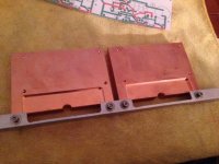
Heat sinks attached to mounting bracket:

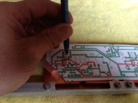
Using printout of the PCB to locate holes for output devices mounting screws:

Ready to drill!:

Drilling the holes in the mounting bracket and heat sinks:
Heat sinks attached to mounting bracket:
Using printout of the PCB to locate holes for output devices mounting screws:
Ready to drill!:
Attachments
I almost always use a fan but feel 4 of them will create too much noise
Even just above the turn on voltage and the slowest speed possible, this might still be too much
But it will defintely keep it cool and very nice work BTW
Regards
David
Even just above the turn on voltage and the slowest speed possible, this might still be too much
But it will defintely keep it cool and very nice work BTW
Regards
David
You might try Velcro instead of rigid mounting the fans to eliminate transmitting anything to the chassis. Rubber won't work as well as this stuff
Fans are light enough to handle Velcro without issue.
To eliminate a beat frequency of so many fans, you might just insert a diode to slow a couple down to spread out any noise contribution
Fans are light enough to handle Velcro without issue.
To eliminate a beat frequency of so many fans, you might just insert a diode to slow a couple down to spread out any noise contribution
Progress, sorta.
I did say this was going to take a while.
It doesn't help when you're breaking drill bits and taps 😡
Anyway, I finished tapping the sinks, made the PCB, and started soldering components. I still have to order a few components before I can start testing...
I've been playing with an LTSpice simulation that I put together and the results to my untrained eyes are looking *meh*. Of course, I have no idea what I'm doing with LTSpice so who knows how predictive it'll be. I'm far enough along that I might as well finish putting it together and let my ears be the judge. If it sucks I'll take out the IRFP150s, solder in 240s, swap out the necessary resistors, and end up with the master's original...
Based on comments in the big ACA thread and recent comments in the F5 thread, I'm giving some thought to thermal protection in case one or more of the fans fails. Simplest, I think, would be two normally-closed thermal switches, in series, per channel to cut off power to the circuit should the MOSFETs approach critical temp. Would require cutting a couple of traces and devising a way to mount the thermal switches, but not much else. Seems too simple. Am I missing something?
Attachments
Your ACA looks way cool (and probably runs way cool too). You probably have overkill on the fans - hope they are not too noisy.
As you saaw, my experiment showed that a single tiny 40mm fan is sufficient to cool two mosfets. The small GPU fans are supposedly quiet at 25dB.
It sounds very good with my XKi PA130 coax speaker. 🙂
As you saaw, my experiment showed that a single tiny 40mm fan is sufficient to cool two mosfets. The small GPU fans are supposedly quiet at 25dB.
It sounds very good with my XKi PA130 coax speaker. 🙂

It's still a work in progress. Still have to order a few components before I can even start testing. Fans are going to run sloooow to minimize noise.
A little progress report...
I had a couple of significant errors in my PCB which led to some component failure, so I've re-thought my approach and, rather than try to correct the errors in my original PCB, I'm doing a re-boot. I've decided I'll do a dual mono amp rather than a stereo amp. Since it's now dual mono, I'm making two separate boards rather than one. This will allow me to complete one channel and work out any kinks before soldering up the second channel. I'll also be making a separate board for the fan controller... this will allow me to swap in a different controller if I find a circuit that I like better. Here's the fan controller PCB (forgot to label P1):

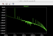
I've included in my new board layout cascode circuitry (stolen from 2PicoDumbs) to reduce the voltage to the 2SK170. While this provides a more stable voltage to the jfet than a simple drain resistor, the simulated FFTs haven't convinced me that this is the way to go. Here's the FFT of the cascoded circuit:

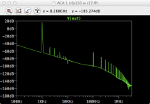
Here's the FFT of the circuit with just a drain resistor:

How will this translate sonically? I don't know. I can use the same board to do either variation, so I'll build one of each and compare them. Simple as that.
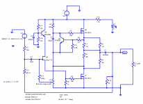
Here's the final (possibly) version of the ACA PCB layout, and the schematic. I was able to shuffle things around enough to make it single-sided. Should be much easier. Hopefully I'll be able to etch the boards this weekend:


Cheers!
I had a couple of significant errors in my PCB which led to some component failure, so I've re-thought my approach and, rather than try to correct the errors in my original PCB, I'm doing a re-boot. I've decided I'll do a dual mono amp rather than a stereo amp. Since it's now dual mono, I'm making two separate boards rather than one. This will allow me to complete one channel and work out any kinks before soldering up the second channel. I'll also be making a separate board for the fan controller... this will allow me to swap in a different controller if I find a circuit that I like better. Here's the fan controller PCB (forgot to label P1):
I've included in my new board layout cascode circuitry (stolen from 2PicoDumbs) to reduce the voltage to the 2SK170. While this provides a more stable voltage to the jfet than a simple drain resistor, the simulated FFTs haven't convinced me that this is the way to go. Here's the FFT of the cascoded circuit:
Here's the FFT of the circuit with just a drain resistor:
How will this translate sonically? I don't know. I can use the same board to do either variation, so I'll build one of each and compare them. Simple as that.
Here's the final (possibly) version of the ACA PCB layout, and the schematic. I was able to shuffle things around enough to make it single-sided. Should be much easier. Hopefully I'll be able to etch the boards this weekend:
Cheers!
Attachments
😀
With a little luck it'll be ready to go for Burning Amp, though it may be presented as a work in progress...
With a little luck it'll be ready to go for Burning Amp, though it may be presented as a work in progress...
- Home
- Amplifiers
- Pass Labs
- ACA Concept II