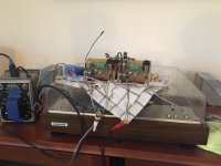
Got a chance to run the amp for a little longer today. Sounds very nice. Will try do do a comparison with the standard ACA at a later date. With the fans running at a very low speed, the heat sinks barely get warm. There's a bit of a hum with a source connected or with the inputs shorted; I'll try to fix that once I get it in its chassis and build a real power supply.
Attachments
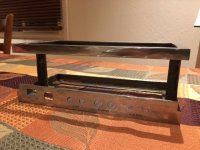
Steel! Hats off to you for making that work.
To answer the question of how to cut rectangular holes in steel? Drill, Dremel, file. Almost as much work as welding two pieces together and smoothing them flat. 🙂
In aluminum, if thin enough use a nibbler tool.
To answer the question of how to cut rectangular holes in steel? Drill, Dremel, file. Almost as much work as welding two pieces together and smoothing them flat. 🙂
In aluminum, if thin enough use a nibbler tool.
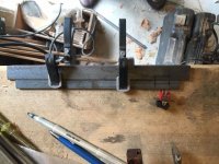
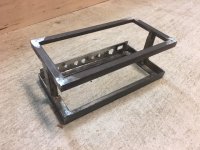
yes, drill, Dremel, file would have worked, but I had to increase the height of the rear rail anyway, so this was the more efficient solution. working with steel sounds daunting, but it's actually very forgiving, since you can work and rework it several times over until you get it right.

Thanks xrk971-
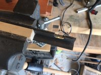
BTW you were right: a little fan cooling goes a long way. There's really no good place to take a reading with my IR thermometer because the output devices are under the PCBs, but pointing it at the exposed OPD mounting screws reads a maximum temp of about 98°F. None of the accessible surfaces get more than lukewarm to the touch. I'll bet I could build a stereo ACA on just one of these sinks & it still wouldn't break a sweat. Hmmm... ACA III? I do have an extra sink in my parts drawer. Would have to make it challenging again. SMD?
BTW you were right: a little fan cooling goes a long way. There's really no good place to take a reading with my IR thermometer because the output devices are under the PCBs, but pointing it at the exposed OPD mounting screws reads a maximum temp of about 98°F. None of the accessible surfaces get more than lukewarm to the touch. I'll bet I could build a stereo ACA on just one of these sinks & it still wouldn't break a sweat. Hmmm... ACA III? I do have an extra sink in my parts drawer. Would have to make it challenging again. SMD?
In a pinch, these old Dell heatsinks can handle 25w no fan and with fan about 60w easily.
Dell F9Y692 0422 Heat Sink Bracket for Dimension 2400 3000 Used | eBay
Only $4 ea. I have like 6 of these - very handy. Nicely made too - thick base.
Dell F9Y692 0422 Heat Sink Bracket for Dimension 2400 3000 Used | eBay
Only $4 ea. I have like 6 of these - very handy. Nicely made too - thick base.
An externally hosted image should be here but it was not working when we last tested it.
Experimenting...
The problem with steel is it rusts. So if you (or your spouse) aren't into the industrial look and would rather not have a hunk of rusting steel in your living room, then you have to protect it somehow. Options are waxing/oiling, clear-coating, painting, powder coating, or plating.
My plan is to go with nickel plating. I've ordered some nickel from China and should receive it in a couple of weeks.
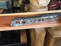
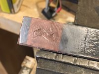
Another part of my plan is to etch the PASS logo and "Amp Camp Amp" on the lower front face of the frame. The etching will be done prior to nickel plating. After nickel plating, I'll copper plate just the etched logo/ACA lettering.
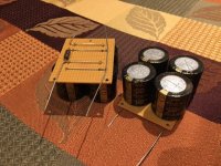
This morning I experimented with electro-etching and localized copper plating. I just used electrician's tape and an xacto to make a simple mask, then etched the design in a piece of scrap steel. After etching, I couldn't replicate the mask (but I will be able to when I do the finished product), so I just copper plated the logo and the surrounding steel. My main goal was finding a way to do localized plating without having to immerse the entire frame, or even a portion, in the plating solution. I'm happy to say I succeeded 😀
Result of my test below. When I get to etching and plating the frame, I'll detail how I did it...

The problem with steel is it rusts. So if you (or your spouse) aren't into the industrial look and would rather not have a hunk of rusting steel in your living room, then you have to protect it somehow. Options are waxing/oiling, clear-coating, painting, powder coating, or plating.
My plan is to go with nickel plating. I've ordered some nickel from China and should receive it in a couple of weeks.
Another part of my plan is to etch the PASS logo and "Amp Camp Amp" on the lower front face of the frame. The etching will be done prior to nickel plating. After nickel plating, I'll copper plate just the etched logo/ACA lettering.
This morning I experimented with electro-etching and localized copper plating. I just used electrician's tape and an xacto to make a simple mask, then etched the design in a piece of scrap steel. After etching, I couldn't replicate the mask (but I will be able to when I do the finished product), so I just copper plated the logo and the surrounding steel. My main goal was finding a way to do localized plating without having to immerse the entire frame, or even a portion, in the plating solution. I'm happy to say I succeeded 😀
Result of my test below. When I get to etching and plating the frame, I'll detail how I did it...
Attachments
Progress... Yes! Welding & grinding of chassis finished, logo & back plate etchings done. Just need final sanding & it will be ready for plating. I have the wood pieces cut to rough dimensions (no pics of that until final reveal... it's special wood). Started work on the cap banks for the PSU. Going to pick up misc. parts for the PSU & also some perforated steel for the chassis tomorrow...
Attachments

Having built the ACA with my daughter my curiosity was piqued and I sat down and spent the last week reading all the Pass articles I could lay my hands on. I have some background in electronics, but sadly it amounts to nothing more than a couple of terms of undergrad physics. After a few days of trawling the forums I found what I was looking for: The Penultimate Zen4 update and this thread.
I would like to employ some of the developments from the Zen articles to take the ACA upscale a bit and was hoping that some generous soul with more experience than I and a knowledge of LTSpice might jump in.
If you have the time to help, I would greatly appreciate your coaching/babysitting. Please PM me.
yours
Beardy
\coaching/babysitting mode on....
I was thinking an ACA turbo rather than starting with Zen 4 because I have one to play with and it seems one could make relatively minor changes using point to point additions to the existing working amp...
Two 19.5V laptop bricks in parallel with some sort of high frequency filter on the input to the rails although I'm not sure whether this is necessary and perhaps the high frequency switching noise is irrelevant..?
Use the existing bias of just over 1A should/may be manageable with existing heat sinks of 0.67 C per W giving a ~26C temperature rise. There are also low cost 16V laptop bricks if 39V is too much of a stretch.
Aleph CS from Zen 2
- I need to understand how to optimize the resistor values for this - do you just build it and use some AC coupled mains 110VAC through a very high value resistor to generate some input. Then measure the voltage drop across the resistors R1-4, calculate current flow and then calculate optimal value for the current source feedback, build it and then recheck? I have voltmeter but not scope.
Cascoded lsk170 on front using 2 PicoDumbs schematic
- I think this is just a case of reading and shamelessly stealing.
Cascoded LU1014D per Zen 8/9/PicoDumbs
- As above. But...
On the cascoded front end shown on 2PicoDumbs Updated Z4 thread, the gate voltage is set by using a fixed voltage divider across the rails. If I understand this correctly the voltage needs to be set so that the output is halfway between the two rails. So does the gate voltage need to be pushed up a little to account for the voltage drop across these two transistors?
Also, if this works then I would like to understand why we use a potentiometer to set this value on the ACA..? I assume the best way would be to have a scope and then use a variable pot and look for symmetric clipping on a scope, but since most people don't have this why would we not just set the value with a pair of matched resistors?
Also, what is the best way to set the same value of the Mosfet when using it to cascode the depletion mode LU1014D: As I understand it with the ACA you just pull the signal up at the gate of the input Jfet and the second stage follows. However, if I use the same sort of fixed voltage divider approach on the Mosfet then it fixes the voltage on the second stage. Is this an issue? does this need to follow the front end, and if so do you reference the bias resistors back to the signal coming off the first stage ?
thanks in advance,
Beardy
Hey all,
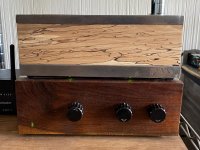
After [checks first post in thread] six and a half years(!) I have an update to this project! The past few years have been challenging, keeping me from continuing ACA Concept II. My son, who was the inspiration for me getting into DIY audio, passed away late in '19. A lot of challenges, both related and unrelated took my attention away from pursuing the hobby.
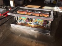
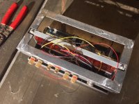
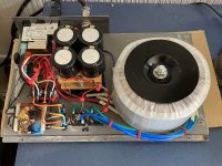
Well, I finally found time, inspiration, and parts to (nearly) bring this project to completion. The last part of the puzzle was the power supply. Simple in concept, but it proved to be more difficult to execute. It has the main PS for the amp, of course, but it also includes a smaller PS for the fans, and for the relays which switch on both the amp and the fans. The PS is connected to the amp via a 9-conductor umbilical, using 16mm 9-pin "aviation" connectors.
The original intention was to have the amp run on 32V, but the finished power supply actually puts out a tad over 26V. Oh well... it still sounds great to my ears. The fans are pretty quiet; they can't be heard at listening distance. The amp does run hot, but I think the heat sinks + fans are doing their job well.
Currently running with input from a B1 built by my son, which I gave to my brother (I'm temporarily crashing at his pad). No complaints about the B1, but I think a preamp with gain would provide a little more oomph. Thinking of trying the H2 V2...
Thanks as always to NP for his boundless generosity, and to Zen Mod for inspiring this -um- mod. I think you owe me a "ly!", ZM 😊
Cheers!
After [checks first post in thread] six and a half years(!) I have an update to this project! The past few years have been challenging, keeping me from continuing ACA Concept II. My son, who was the inspiration for me getting into DIY audio, passed away late in '19. A lot of challenges, both related and unrelated took my attention away from pursuing the hobby.
Well, I finally found time, inspiration, and parts to (nearly) bring this project to completion. The last part of the puzzle was the power supply. Simple in concept, but it proved to be more difficult to execute. It has the main PS for the amp, of course, but it also includes a smaller PS for the fans, and for the relays which switch on both the amp and the fans. The PS is connected to the amp via a 9-conductor umbilical, using 16mm 9-pin "aviation" connectors.
The original intention was to have the amp run on 32V, but the finished power supply actually puts out a tad over 26V. Oh well... it still sounds great to my ears. The fans are pretty quiet; they can't be heard at listening distance. The amp does run hot, but I think the heat sinks + fans are doing their job well.
Currently running with input from a B1 built by my son, which I gave to my brother (I'm temporarily crashing at his pad). No complaints about the B1, but I think a preamp with gain would provide a little more oomph. Thinking of trying the H2 V2...
Thanks as always to NP for his boundless generosity, and to Zen Mod for inspiring this -um- mod. I think you owe me a "ly!", ZM 😊
Cheers!
Attachments


- Home
- Amplifiers
- Pass Labs
- ACA Concept II