In case that somebody likes to build the "Premium Parts ACA#1":
I offer you a pair of the "PremiumParts - ACA#1 PCBs" (size is 100 x 80mm) for 15€ plus shipping.
Be sure: the PCB is proved and its sound is absolutely irresistible.
Best regards - Rudi_Ratlos
I offer you a pair of the "PremiumParts - ACA#1 PCBs" (size is 100 x 80mm) for 15€ plus shipping.
Be sure: the PCB is proved and its sound is absolutely irresistible.
Best regards - Rudi_Ratlos
Attachments
James, in post #88 you are telling that the bridge-rectifier that you have ordered, drops about 1.5V per active diode (resulting in about 3V across the bridge amplifer).
In the meantime I have done the layout for a "discrete MUR8x0 - rectifier", including snubber RCs.
I have ordered the PCBs today (one PCB containing two full-bridge rectifiers, having the same height as the ACA - PCBs, you can break the PCB with your fingers) and
I will send you a PCB (for nothing, of course, but shipping cost, if you like to have) as soon as I have them.
Best regards - Rudi
Attachments

Nice layout Rudi, on the rectifier PCB (and your amp PCB as well). One point is that since there are 2 rectifiers bolted either side of the TO220 heatsink with a common screw, one will need to insulate the TO220 devices with TO220 Keratherm pads and use Nylon screws. Or use the newer fully insulated TO220 devices - one being the MURF860G (600V at 8 amps), available at both Mouser and Digikey, and slightly cheaper than the non insulated normal TO220 package. I would still use a thin smear of good heatsink compound with these newer devices for best heat transfer.
There is also a very good white paper available on diode snubber circuit design which I am sure has been posted previously on this forum, maybe another member has a link for it.
There is also a very good white paper available on diode snubber circuit design which I am sure has been posted previously on this forum, maybe another member has a link for it.
One question Rudi, on the Amp PCB what is the maximum diameter for the 3 off large snap in electrolytic capacitors?
The grid of the 3 "big" capacitors on this PCB is 10mm, the max. diameter is 25mm.
Best regards - Rudi
P.S.: What is not shown on the image, but what I always do: to bypass the "big" output capacitor C1 by a small MKP (470nF - 1µF) underneath the PCB.
Best regards - Rudi
P.S.: What is not shown on the image, but what I always do: to bypass the "big" output capacitor C1 by a small MKP (470nF - 1µF) underneath the PCB.
Last edited:
ACA-220 v1
As a brief recap of my work so far, here is a quote of mine from another thread:
The newly configured ACA-220 v1 conveys remarkable Pace, Rhythm & Timing, and remains enjoyable for extended listening sessions with a variety of music styles and sources. This amp seems to do a better job of showcasing the advantages of LPs pressed for 45 rpm instead of 33 1/3. Subjectively it has the same overall gain and dynamics of the parallel bridged monoblocks, but has a remarkable ease and fluidity while achieving plenty of volume for the way I like to listen. My speakers, my living room. I would need to analyze the amp with test equipment before making hard claims about gain and frequency response.
I will note that the Antek AS-3222 toroids are rated for 6.8 Amps on each secondary and exhibit no voltage drop at the inputs of the bridge rectifier. The voltage at each reservoir cap is due to diode drops under load. For this particular application, a 200VA transformer with good 22V secondaries would probably also work. Using a different filter configuration could allow for 20V or even 18V secondaries, depending on the voltage one wished to supply to each board. I have found that having 24.8V on the ACA power rail is a good way to go.
As a brief recap of my work so far, here is a quote of mine from another thread:
Since that time I have increased the reservoir capacitors to 36000 uF. This gave a modest but worthwhile improvement to the sound. I have also substituted Vishay VS-26MB40A (25A, 400V) bridge rectifiers. These exhibit a slightly reduced voltage loss under load, and seem to help the amp sound better. The combination of these last two tweaks has given me an amp that compares very favorably with the parallel bridged ACA monoblocks (w/ SMPS) that had become my benchmark.The first build (ACA-220 v1) used an Antek AS-3222 toroidal transformer feeding a 24000 uF reservoir capacitor through On Semiconductor GBPC3504 bridge rectifiers for each channel. This resulted in about 27 Volts at the terminals of the reservoir caps, rather than the 28+ Volts that I was expecting. While 1.0 or 1.2 Volts may not seem like much, it eats into the headroom needed to produce a solid, low ripple 24.6 Volts to the amp.
After some experimentation, I have currently settled on 1.5Ω Ohms for the power resistor after the reservoir cap. This was about the minimum value that still provided good ripple reduction. A value of 2.26Ω yielded lower ripple, but at the expense of lower voltage to the amp. Space on the modified ACA boards permits a pair of 10000 uF, 50V filter caps, with a pair of parallel 0.22Ω resistors before the second of the two filter caps. The 1.6 Amp quiescent current of the modified ACA accounts for the voltage loss through the resistors, and also through the rectifiers. This overall PSU setup seems to be a "sweet spot" for good sound, resulting in an amplifier that is a pleasure to listen to.
The newly configured ACA-220 v1 conveys remarkable Pace, Rhythm & Timing, and remains enjoyable for extended listening sessions with a variety of music styles and sources. This amp seems to do a better job of showcasing the advantages of LPs pressed for 45 rpm instead of 33 1/3. Subjectively it has the same overall gain and dynamics of the parallel bridged monoblocks, but has a remarkable ease and fluidity while achieving plenty of volume for the way I like to listen. My speakers, my living room. I would need to analyze the amp with test equipment before making hard claims about gain and frequency response.
I will note that the Antek AS-3222 toroids are rated for 6.8 Amps on each secondary and exhibit no voltage drop at the inputs of the bridge rectifier. The voltage at each reservoir cap is due to diode drops under load. For this particular application, a 200VA transformer with good 22V secondaries would probably also work. Using a different filter configuration could allow for 20V or even 18V secondaries, depending on the voltage one wished to supply to each board. I have found that having 24.8V on the ACA power rail is a good way to go.
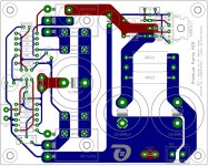
Gentlemen, I have a pair of the "Premium Parts ACA" - PCBs, the PCBs that TungstenAudio is evaluating, left (image 1) and will offer it to you.
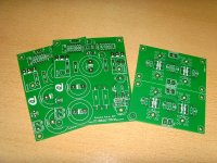
I will include a pair of MUR8x0 full-bridge rectifiers as well (the PCB on the right side of image 1, which can be easily broken apart).
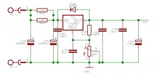
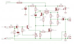
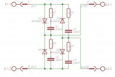
I have included images of the used schematics (images 3 - 5).
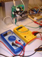
The assembled ACA-PCB will finally look a lot like on image 2 (showing the phase of adjusting the quiescent / bias current).
In my opinion Mr. Nelson Pass' ACA is an amplifier that "begs" for a regulated PSU (needing 1.4A - 1.8A of current).
This is the reason why I have inserted a LT1084 voltage regulator (adjusted to 24VDC) on these PCBs.
If you are interested to have these 2 PCB-pairs (2 x ACA + 2 x full-bridge rectifier: I offer them for 15€, worldwide shipping included): give me a PM.
Best regards - Rudi_Ratlos
I will include a pair of MUR8x0 full-bridge rectifiers as well (the PCB on the right side of image 1, which can be easily broken apart).
I have included images of the used schematics (images 3 - 5).
The assembled ACA-PCB will finally look a lot like on image 2 (showing the phase of adjusting the quiescent / bias current).
In my opinion Mr. Nelson Pass' ACA is an amplifier that "begs" for a regulated PSU (needing 1.4A - 1.8A of current).
This is the reason why I have inserted a LT1084 voltage regulator (adjusted to 24VDC) on these PCBs.
If you are interested to have these 2 PCB-pairs (2 x ACA + 2 x full-bridge rectifier: I offer them for 15€, worldwide shipping included): give me a PM.
Best regards - Rudi_Ratlos
Attachments

ACA-220 w/LM1084
Having reached a certain point of satisfaction with my ACA-220 v2 project (which will be described in a separate post), I decided it was time to circle back to the question of the IC regulator. The prototype PCBs which were used for ACA-220 v1 already included a space for a LM1084 regulator, and I had already installed most of the supporting components in preparation for making the comparison with unregulated vs regulated performance. So I installed the 3-pin IC, along with a Nichicon 470uF, 50V KA type cap on its output. Since the regulator requires at least 1.5V of headroom, I also needed to change the power resister after the main reservoir cap from 1.5Ω to 0.25Ω. The regulator was then adjusted to give the same rail voltage to the ACA circuit as it had been getting from the straight CRCRC configuration.
After making the changes, I spent a few listening sessions evaluating the result. Since the ACA-220 v1 has become my new benchmark, I am very familiar with its sound. Compared with that configuration, inserting the regulator into the power supply was a step backward. In particular, the soundstage lost some of its three-dimensional presentation, and percussion instruments lost some of their visceral attack. Typically when I'm listening to v1, I tend to forget about everything else and just listen to all the tracks on an album. (I often sit in my listening chair with an iPad at hand to read news or research components for the next build.) While listening to the regulated configuration, I tended to skip to different tracks and different albums, just trying to get a feel for what all sounded different. Bringing the new v2 configuration online served to remind me of what was missing.
Perhaps it is more fair to compare the regulated ACA with one of the original builds. I did so by removing the parallel bridging jumpers from one of my ACA monoblocks and spent some time with that. The simple stereo ACA is still a wonderful amp, and I like how my original set of modifications has shaped the sound. The regulated ACA preserves this sound, and seems to give a little better channel separation. (single SMPS brick vs dual secondary windings + regulation)
Those of us who have built a pair of ACAs and run them in one of the bridged configurations know that the monoblocks sound greater than just the sum of two amps would suggest. This is the sound that I've been trying to equal or better with my recent builds. The ACA-220 v1 in my system sounds like a pair of parallel bridged monoblocks, with increased dynamic clarity. The soon-to-be discussed v2 sounds even better. The regulated ACA has a place within this lineup, as it provides a fairly straightforward means of getting very good sound from a transformer-based linear PSU. It may also be a solution where the mains AC is particularly dirty or suffers from fluctuations in voltage. However, it would seem that IC-based regulation is something of an evolutionary dead-end with regards to ultimate sound quality. Going to a full discrete regulator implementation or other regulated topology may be a different story.
Looking forward to more updates on your V2 build of the premium ACA - perhaps with an updated schematic showing any changes with a BOM.
I have attached a marked up schematic of the enhanced ACA which has been the basis for my latest builds. This is the same one I posted a few pages back and includes my notes on the components that I have been using. The red markups are the original modifications that I made, and still represent the ACAmps that I have configured in parallel bridged mode. The blue markups show the basis for the ACA-220 modifications. The significant change is the addition of R16, which reduces the voltage to the input JFet and along with C4 at 100 uF, also filters the power to that component. It's a small change, but has given me some peace of mind when using higher voltage power supplies.
The PCBs I have been using recently were done by Rudi. I bought a set of six boards for my builds using the Hafler chassis, and have ordered another set of boards with his updated layout. These will be development platforms for further experiments using the Modushop Mini 3U chassis and various power supply configurations. Rudi has provided layout diagrams and schematics for the new PCBs. My older version of the PCBs had a different grounding scheme in the regulator section (which I prefer), and also had a place for a second JFet in parallel with Q4. The purpose of this was to have a means of evaluating alternate devices to be used in parallel to get the necessary Idss and transconductance.
Most of the modifications are easy to implement on the current ACA 1.6 boards being sold in the diyAudio store. R16 is a bit more tricky, since it would require cutting a trace in the right place. Possibly installing a jumper as well; I haven't looked at the backs of those boards for a long time. I would like to suggest that if there is an opportunity to modify the ACA 1.6 layout, the new one could include spaces for R16 and C101. Those are the only two additions to the board. All other modifications are component substitutions that use the existing component footprints. The stock design is easily achieved by jumpering R16 (or simply installing a 100Ω resistor), and leaving C101 blank.
Without the explicit need for an IC regulator, except under special circumstances, the rest of the power supply may be implemented separately from the amplifier circuit. I have been getting excellent results with a CRCRC configuration. For the enhanced ACA, I would recommend starting with a 200VA transformer with 20V or 22V secondaries, and working up from there.
The recipe for my ACA-220 v1 is 300VA transformer w/ 22V secondaries (Antek AS-3222)
Vishay VS-26MB40A Vishay Semiconductors | Mouser bridge rectifiers
Kemet 36000 uF, 40V screw terminal reservoir capacitor ALS70A363DE040 KEMET | Mouser
Vishay 1.5Ω, 25W power resistor RH0251R500FE02 Vishay / Dale | Mouser
And a pair of CDE 10000 uF, 50V snap-in filter caps, which could be replaced by Kemet screw terminal ALS80A103DB063 KEMET | Mouser. I use a pair of 0.22Ω, 2W resistors between the 10000 uF filter caps.
The magic lies as much in the power supply as in the amplifier circuit.
That is great! Thanks.
Just for the complete newbies... could you share the PSU diagram (not only the BOM)? Perhaps for most, your info is enough to conjure up a PSU... that is NOT the case for some of us 🙂
Thanks a lot! Best regards,
Rafa.
Just for the complete newbies... could you share the PSU diagram (not only the BOM)? Perhaps for most, your info is enough to conjure up a PSU... that is NOT the case for some of us 🙂
Thanks a lot! Best regards,
Rafa.

Having reached a certain point of satisfaction with my ACA-220 v2 project (which will be described in a separate post), I decided it was time to circle back to the question of the IC regulator. The prototype PCBs which were used for ACA-220 v1 already included a space for a LM1084 regulator, and I had already installed most of the supporting components in preparation for making the comparison with unregulated vs regulated performance. So I installed the 3-pin IC, along with a Nichicon 470uF, 50V KA type cap on its output. Since the regulator requires at least 1.5V of headroom, I also needed to change the power resister after the main reservoir cap from 1.5Ω to 0.25Ω. The regulator was then adjusted to give the same rail voltage to the ACA circuit as it had been getting from the straight CRCRC configuration.
After making the changes, I spent a few listening sessions evaluating the result. Since the ACA-220 v1 has become my new benchmark, I am very familiar with its sound. Compared with that configuration, inserting the regulator into the power supply was a step backward. In particular, the soundstage lost some of its three-dimensional presentation, and percussion instruments lost some of their visceral attack. Typically when I'm listening to v1, I tend to forget about everything else and just listen to all the tracks on an album. (I often sit in my listening chair with an iPad at hand to read news or research components for the next build.) While listening to the regulated configuration, I tended to skip to different tracks and different albums, just trying to get a feel for what all sounded different. Bringing the new v2 configuration online served to remind me of what was missing.
Perhaps it is more fair to compare the regulated ACA with one of the original builds. I did so by removing the parallel bridging jumpers from one of my ACA monoblocks and spent some time with that. The simple stereo ACA is still a wonderful amp, and I like how my original set of modifications has shaped the sound. The regulated ACA preserves this sound, and seems to give a little better channel separation. (single SMPS brick vs dual secondary windings + regulation)
Those of us who have built a pair of ACAs and run them in one of the bridged configurations know that the monoblocks sound greater than just the sum of two amps would suggest. This is the sound that I've been trying to equal or better with my recent builds. The ACA-220 v1 in my system sounds like a pair of parallel bridged monoblocks, with increased dynamic clarity. The soon-to-be discussed v2 sounds even better. The regulated ACA has a place within this lineup, as it provides a fairly straightforward means of getting very good sound from a transformer-based linear PSU. It may also be a solution where the mains AC is particularly dirty or suffers from fluctuations in voltage. However, it would seem that IC-based regulation is something of an evolutionary dead-end with regards to ultimate sound quality. Going to a full discrete regulator implementation or other regulated topology may be a different story.
Hey Tungsten,
I have been reading your adventures with interest and was surprised by the results of the regulator version. Then I looked at the data sheet and noticed that the transient response is pretty bad so I am wondering if it would benefit from increasing the 470uF cap to like a 10,000 uF.
I am currently using a ACA 1.6 built per plans driving some 4 ohm speakers at my desk. I like the description of your improvements and will try them on my stock boards. Since I have very little room for amplifiers dual mono blocks won't work. So I keep trying to figure out how I can get two parallel amps in one box (3U or 4U?)?
Still have a couple projects to finish first though, like my mag-lev speaker stands. Thanks for the inspiration and keep us posted.
David.
Yes, I am pretty convinced that I was running up against the transient response or 'speed' of the LM1084. It actually does quite well for an integrated part in a 3-pin TO-220 package. The surprising part may be that a Class A amplifier needs a fast regulator. It turns out that the typical FirstWatt style PSU that we've been using for various clones has a very low output impedance over a broad frequency range. It would be very difficult for an error amplifier / pass transistor type circuit built on a single IC to match this performance. I pretty much knew that going in, which is one of the reasons why I spent more time beforehand building a solid PSU that didn't rely on regulation.
One of the big takeaways is that yes, a Pass Labs class A amp needs a good low impedance PSU to perform its best.
A discrete regulator design to watch is AMB Lab's Sigma 11. I have already been very satisfied using this circuit (with appropriate cap upgrades) to power my main preamplifier. So, yes, it greatly exceeds the best LM317 regulator design that Naim uses for their first couple tiers of preamp PSUs. Naim's own NAP 250 and NAP 300 power amps also use bespoke discrete regulators to provide clean power for their amp circuits. The size of the regulator boards and pass transistors are the same as the main amplifier. The Sigma 11 is about the same size as one channel of an ACA, so it could work. 😉
@baggerbole,
yes ... please take a look https://www.diyaudio.com/forums/pass-labs/328357-aca-amp-premium.html#post5565902 and there was another post but I didn't find them ...
yes ... please take a look https://www.diyaudio.com/forums/pass-labs/328357-aca-amp-premium.html#post5565902 and there was another post but I didn't find them ...
James, I am not with you this time.
1st: The LM / LT 108x series of voltage regulators is famous for / optimized for their fast transient response time (and low dropout).
Talking about transient response: we are talking about slightly more than 10µs of reaction time due to a change of load!
2nd: Transient Response time is imho not a sincere concern, when we are dealing with ClassA amplifiers.
The "quiescent / bias" current of the ACA with your modifications operated from a 24VDC PSU (regulated PSU or not) is about 1.4A.
During operation some 100mA of current are added.
Given a strong transformer (I am currently using a 2x20VAC / 200VA torroid) and sufficiently big reservoir caps,
the additional mA need not be taken into account.
3rd: I have listened to my LM1084 ACA, then I have put a short betwen in- and output of the regulators pins (resulting in a C-R-C PSU) and listened again.
The track that I have listened to: a live performance of Diana Krall in a relatively small concert hall, and while she was singing
somebody upset a glass (of beer 🙂) .
In my ears: the LM1084 ACA sounded more natural, more precise than the C-R-C ACA.
I could hear the clinking of the glass, … The C-R-C powered ACA sounded more "metallic", ….
Of course: "Sound" is individual!
My setup is: CDP, ALPS-Blue-Velvet Potentiometer attenuation, ACA, KEF Q1 Speakers (8 Ohms impedance).
And this varies a lot from your Setup!
But it made fun to find out, what pleased me most!
Best regards - Rudi
- Home
- Amplifiers
- Pass Labs
- ACA amp with premium parts