Starting gluing down wires tonight... I'm averaging about 20 wires/hr....hopefully I will find faster ways to do it as I continue on 🙂
Starting gluing down wires tonight... I'm averaging about 20 wires/hr....hopefully I will find faster ways to do it as I continue on 🙂
My welding rod stators were likewise a PITA. You must be gluing them down in groups. I put all the rods on the grid at once, with a about 8 threaded rods keeping them properly spaced, then started from one end running beads of glue across them, until they were all done.
You will be happy with the results.
I am putting them down in groups...
I tried putting a bunch down all at once it seemed almost impossible to line them up.
I tried putting a bunch down all at once it seemed almost impossible to line them up.
Also going to try a radiator fin comb to help "comb out" the wires to align them.
For the sake of clarity I will call the welding rods wires. Now, try this:
[rather than placing a bunch of wires onto the plastic grid and then trying to sort them with the all-thread rod] place an all-thread rod across one end of the plastic panel grid, and then insert wires one at a time between the threads and plastic grid. Once you have all wires thus placed and sorted at one end, place a another all-thread rod just ahead of the first one-- then slide it forward to comb out the wires, placing additional all-thread rods down as you go.
That is exactly I was discovered towards the end of my session... just slide them down and "thread" them thru the threads of the threaded rod (lot of threads there 🙂 ).
The tricky part with using the all thread as a comb, is that the wires want to move on you (as the move thru the spirals). Sure I will be pro soon enough 🙂
The tricky part with using the all thread as a comb, is that the wires want to move on you (as the move thru the spirals). Sure I will be pro soon enough 🙂
So on the transformer front, the 2 winding shops I contacted have went silent on me... so guess they aren't interested in my business....
Looks like I may have to go with the generic torodial power transformers. I was thinking about using 3 of these per speaker (115:1 step ratio total).
Any problems with this approach or these transformers?
VTX-146-015-106 - MULTICOMP - Toroidal Transformer, 28mm x 60mm, 15 VA, 2 x 6V, 1.25 A, Chassis | Farnell element14
Hi bengel
They should be fine - but you will need an even number on each speaker.
Put all the low voltage windings in parallel -just make sure the pairs on each transformer are all the same phase so they don't short the amp🙂. 6Vac rating at 50 Hz on the input side will give you 30Vac rating at 250 Hz - so that looks very good.
On the high voltage side put all of the 230Vac windings in series. The high voltage polarising voltage (2.6 kV - dc ?) must be 'grounded' at the centre of the high voltage windings so that the stators are operating in a properly balanced push-pull arrangement. That means an even number of transformers is required. Four transformers per speaker - two HV windings on each side of the HT should be good.
The overall step-up ratio will be about 153, which is also very nice. If these transformers are anything like the 15VA transformers I measured the secondary leakage inductance will be about 64 mH and the winding capacitance about 65 pF - bandwidth should be very good, and will be very forgiving of the amplifier.
regards
Rod
If an even number of transformers is not possible, you can always use a virtual center tap for the polarizing voltage connection.…The high voltage polarising voltage (2.6 kV - dc ?) must be 'grounded' at the centre of the high voltage windings so that the stators are operating in a properly balanced push-pull arrangement. That means an even number of transformers is required. Four transformers per speaker - two HV windings on each side of the HT should be good.
I have used it with a couple ESL setups and found no change in distortion or output level relative to using a “proper” center tap.
http://www.diyaudio.com/forums/planars-exotics/279534-no-ct-transformer-bias-return.html#post4445639
Are those number for 1 toroid? Or 4 toroids with 6V windings in parallel and 230V windings in series.If these transformers are anything like the 15VA transformers I measured the secondary leakage inductance will be about 64 mH and the winding capacitance about 65 pF - bandwidth should be very good.
64mH just seems like a lot of leakage inductance for one toroid.
If it is for one toroid, must be a LOT of insulation between primary and secondary, or perhaps only partial coverage of the core by the 6V windings?
The figures for the leakage inductance and winding capacitance are for the four transformer connected together.
Woofer box (or how does Logan/Sanders do it?)
So on a different topic (which may belong in a different forum) I am starting to think about the speaker woofer box design.
Currently thinking about 2 approaches....
1) Box (precise volume TBD) with drivers mounted in front and back (kinda dipole-ish) in a push-pull config (out of phase).
That would be the easier approach.
But what I would like to do is....
2) a transmission line setup. The problem here is to get down to even 40hz, a quarter wave is quite long.
So curious how Martin Logan and Sanders is about to use such a design with such small boxes?
All of the design guidelines and research suggests that it would be impossible to do right in such a small box.
Looking at this cut away, the line "tapers" dramatically.
http://www.hifimusic.co.il/download/file.php?id=1917
Hi again Bengel,
WOW! I thought Sanders' compact TL was pretty small but I've never seen one as tiny as the ML pic you just posted... and I can't imagine it would perform well.
I've never heard Sanders' speakers but he claims they are flat to 22Hz and they have received great reviews in the audio press.
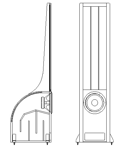
If I had seen Sanders' compact design before I built my beam splitters I may have gone that direction instead. As it was, I was pretty pleased with my beam splitters but I wanted to post an easier-build design on my blog so I drew up a design based on Sanders' TL; which I call the Eros Clone.
If you're interested I have a fully dimensioned 2-D DeltaCad drawing of the Eros Clone design. I've never built it, never heard it so I can't say how well it would perform but it's a pretty close approximation of Sanders' TL. Below are front and side views pulled out of my drawing:
WOW! I thought Sanders' compact TL was pretty small but I've never seen one as tiny as the ML pic you just posted... and I can't imagine it would perform well.
I've never heard Sanders' speakers but he claims they are flat to 22Hz and they have received great reviews in the audio press.
If I had seen Sanders' compact design before I built my beam splitters I may have gone that direction instead. As it was, I was pretty pleased with my beam splitters but I wanted to post an easier-build design on my blog so I drew up a design based on Sanders' TL; which I call the Eros Clone.
If you're interested I have a fully dimensioned 2-D DeltaCad drawing of the Eros Clone design. I've never built it, never heard it so I can't say how well it would perform but it's a pretty close approximation of Sanders' TL. Below are front and side views pulled out of my drawing:
Yeah, the Logans are mystery to me as well.... don't get the passive crossovers and the TL looks completely inadequate... but what do I know. I suspect people are so blown away by the ESL, the bass performance is a bit overshadowed.
One thing I am trying to find some understanding about is Sanders talks in his white paper that transmission lines are superior in bass because of transient response and that closed boxes perform poor because of the compression and then "overshoot" of the driver (poor control).
The thing is, if you are using active crossovers instead of passive crossovers, good amps will have monster control over the driver.... i.e. my amp has a damping factor of 400 and since I am using active crossovers, it can use all of it.
Using passive crossovers can cut amp damping/control over a driver by factors of hundreds (due to the inductors/resistors in the signal path).
So, do TL's REALLY perform better in transient response than traditional/ported designs with an active crossover? A TL would certainly be vastly,vastly superior in transient response over a closed/ported designs with passive crossovers.
I would love to have that drawing but I don't have delta CAB. Not sure if you can export into a format I can open with a freebie CAD viewer.
BTW the driver I would like to use is my extremis mid-woofer, which is a 7" driver and like to design for a 250hz to 40hz - ish response.
Thanks so much... now back to gluing wires 🙂
First thing to realize about the ML Vantage is that its woofer has its own amplifier built into the backplate. So, it can be equalized for extended bass in a small cabinet. That alone probably removes most of the mystery. The bass loading is not a TL, rather a traditional vented enclosure. What you are seeing is a really long slot port. The “box” that the woofer is in looks to be about 0.5 – 0.6 ft^3. With the slot port having an area of about 10 – 12 in^2, you need 40 – 50 in length to tune to 35 Hz which fits into the space by folding it back and forth. Why 35 Hz? Note the knob on the back that lets you dial in bass boost centered at 35 Hz. If the port is tuned to 35hz, the woofer will be highly loaded at that frequency and excursion will be minimized. So, you can get much more 35hz thump out of the smallish 8” woofer than you would ever expect.Yeah, the Logans are mystery to me as well.... don't get the passive crossovers and the TL looks completely inadequate...
Any enclosure modeling tool will show that the Sanders white paper is physically incorrect. At low frequencies a sealed enclosure simply acts as an air spring which is in parallel with the spider (mechanical spring) to define a combined suspension stiffness. I have never measured a transmission line woofer enclosure with better transient response than a woofer in a properly sized sealed box. It can come close if a lot of damping is used in the line. With light damping the transient response looks more like that of a vented enclosure. So why use them? If properly sized and damped, TL enclosures can give you a boost in efficiency over a broader bass range than a vented enclosure. Cone excursion is also reduced at tuning similar to a vented enclosure but again over a broader frequency range. One other advantage is that TL enclosures tend to be inherently well braced because of all the internal boards used to make the line. Most people don't put that much effort into bracing "simple" sealed boxes.One thing I am trying to find some understanding about is Sanders talks in his white paper that transmission lines are superior in bass because of transient response and that closed boxes perform poor because of the compression and then "overshoot" of the driver (poor control).
With that small of a woofer, you definitely would benefit from a TL enclosure to keep the cone excursion down at lower frequencies.BTW the driver I would like to use is my extremis mid-woofer, which is a 7" driver and like to design for a 250hz to 40hz - ish response.
Currently thinking about 2 approaches....
1) Box (precise volume TBD) with drivers mounted in front and back (kinda dipole-ish) in a push-pull config (out of phase).
2) a transmission line setup. The problem here is to get down to even 40hz, a quarter wave is quite long.
1) with woofers on front and back running up to 250Hz, you will likely have cancellation issues at some discrete frequencies due to the acoustic path difference to the listener.
2) Tapering the line area will increase the effective acoustic length of the line, so you don't have to build it a physical 1/4 wavelength. Are you interested in getting into modeling of enclosures? or more looking for an existing design to increment off of.
Last edited:
With that small of a woofer, you definitely would benefit from a TL enclosure to keep the cone excursion down at lower frequencies.
This is true but I do have one thing going for me. This driver has a 26mm XMAX and with the XBL^2 tech Dan Wiggins designed into it, the BL is very flat across the range of that 26mm (low distortion near max excursion).
However, I do start getting into problems when they are driven to their limits
The inductance is also very low for this driver, which equates to better transient response (it's not the "mass" of the cone, it is the inductance that defines better transient response).
Here is an article by Wiggins on the topic I dug out of my bookmarks (yeah, I am a Dan Wiggins fanboy 🙂 ).
http://www.adireaudio.com/Files/WooferSpeed.pdf
I really do love these drivers for bass in my current MTM speakers I built. With the active crossovers, they sound amazing..... and I am very picky about bass quality sound reproduction 🙂. So I am trying to "reuse" them because of how good they sound.
Having said all of that, I can't seem to find a design I like using the unibox spreadsheet. I've tinkered around with it for the past few weeks and seems I keep running into problems.
So I may just have to throw in the towel and get a good 10" sub driver and use a TL design. I do recognize that I only need it to be good between 40-250hz and I don't care about its higher "mid range" capabilities.
(looking at this one in particular https://www.parts-express.com/pedocs/specs/295-460-dayton-audio-rss265hf-4-specifications-46172.pdf)
2) Tapering the line area will increase the effective acoustic length of the line, so you don't have to build it a physical 1/4 wavelength. Are you interested in getting into modeling of enclosures? or more looking for an existing design to increment off of.
Honestly, at this point, I don't. I am up to my eyeballs in the ESL design aspect of this. I would rather leverage off of existing designs. CharlieM has been nice enough to send me a design based off of the Eros design. So may just go with that.
I was hoping there would be some sorta "kindergarten" calculator to design a TL, looks like it won't be that easy 🙂. Lenard Audio's program is pretty good but still pretty deep 🙂
I built a tapered TL using a Hi Vi D8.8. I tried sealed and vented, lived with each type for over a year each. The sealed was bad and the vented OK.
I am very happy with the TL.
The line was folded 3 times, making it about 60 cm high (or wide). I chose the dimensions to fit in the bottom of the 60cm wide ESL III (below the panels where the electronics are). I used to use a minidsp on the sub and ran the panels full range. I now have a minidsp 2x8 and cross over to the panels at 200 Hz. I never got around to moving the ESL TX/HVPS and used the subs upright behind the panels.
They work the same way with the Kings and I'm considering what to do with the ESL III.
An 8 to 10" with similar T/S parameters would work well.
http://www.diyaudio.com/forums/subwoofers/241546-hivi-d8-8-tl.html
kffern
PS. I used the "alignment table calculator" spreadsheet I found on diyaudio. I cross checked with martins paper and it was fine. See the thread and it was proven a good match by others.
Last edited:
Hi,
did that TL thing about 30years ago and also in conjunction with ESLs.
As Bolserst already said is the claimed superiority against closed boxes a myth.
My guess why a TL might be thought apropriate for an ESL is, that its deep but soft noted bass shares similarities to the soft noted bass of a Fullranger ESL.
But this kind of Bass is neither correct nor really good.
Also the classic bulky TLines were rather low in efficiency, which made pairing with an inefficient Panel easy.
If the Panel is designed consequently for hybrid useage one needs a more efficient woofer or needs to go active.
The latter case allows for more options to chose from, like reduction of cabinet volume, easy equing, etc.
If the effort should remain reasonably low I'd opt for a active, small sized closed box and rather add a second bass driver than anything else.
I've never heard a TL -and even less so a BR- that really integrated well with an ESL Panel, neither optically nor acoustically.
Regarding driver size I'd orientate at the Panel width and its lower bandwidth limit and the room situation.
It seems that a good 8" and certainly many 10" will fit the bill.
Don't try to squeeze the lowest Hz from the driver.
50-40hz as lower bandwidth limit will almost always give You better sonic results for 95% of Your listening time than a 30-20Hz design.
jauu
Calvin
Quick question for Bolserst on his spreadsheet:
When you select "Finite" as the type of line source, how far off the floor does it presume the panel will be?
When you select "Finite" as the type of line source, how far off the floor does it presume the panel will be?
When you select "Finite", the assumption is that the panel is in free space far away from all room boundaries. I'm sure the follow-up question is how close do you have to get the panel to the floor before you start picking up some benefit on the low end due to the floor image. Unfortunately I don't have a good set of measured data to be able to quantify that, although I hope to sometime later this year. My guess is that you would need to get within 1/4 the panel height to start picking up significant benefits.
When you select "Finite", the assumption is that the panel is in free space far away from all room boundaries. I'm sure the follow-up question is how close do you have to get the panel to the floor before you start picking up some benefit on the low end due to the floor image. Unfortunately I don't have a good set of measured data to be able to quantify that, although I hope to sometime later this year. My guess is that you would need to get within 1/4 the panel height to start picking up significant benefits.
I am just concerned about that wicked roll off shown on the graph at my listening distance (-6dB from 1kHz to 250hz).
Guess I shouldn't care too much as my room correction prepro will fix it.
- Home
- Loudspeakers
- Planars & Exotics
- About to take the ESL plunge