Golfnut:
If I were to request a quote for a custom toroidal stepup transformer, for say a 150:1 ratio, what would be the ideal? I am also thinking about this in terms of what would make a good general purpose torodial step up for hybrid ESL builders?
I may weep when I see the price quote but thought it worth a shot. I was looking at these guys (sure there are dozens of companies out there). Toroidal Transformer General Design Specifications - Butler Winding
BTW the vigortronix transformers are on back order until April. I may just have to wait it out or pay up for specialized ESL transformers.
So given my panel specs.... what would be the be combo of transformers to use?
Vigortronix 230V Toroidal Transformers Single Primary Dual Secondary | Rapid Online
So given my panel specs.... what would be the be combo of transformers to use?
Vigortronix 230V Toroidal Transformers Single Primary Dual Secondary | Rapid Online
BTW the vigortronix transformers are on back order until April. I may just have to wait it out or pay up for specialized ESL transformers.
So given my panel specs.... what would be the be combo of transformers to use?
Vigortronix 230V Toroidal Transformers Single Primary Dual Secondary | Rapid Online
If you don't find what you're looking for I have (4) of those 50VA 230V/2x6V Vigortronix transformers and (2) 2.7KV bias supplies assembled, tested and ready to roll; which I would be willing to part with. They've got maybe an hour of use (bought them for testing purposes). It's the very same ones shown on my website.
I read in one of Golfnut's posts recently that the 50VA toroids are more optimal for un-segmented panels. However, I'm using them on my segmented panels and they sound fine.
Electrostatic Speaker Toroids.......
if you got deep pockets....these are to be...some of the best...good luck
if you got deep pockets....these are to be...some of the best...good luck
Electrostatic Speaker Toroids.......
if you got deep pockets....these are to be...some of the best...good luck
Ha..... not that deep 🙂. I figured I'd start cheap then maybe I will get upgrade-itis at some point and fork over the big bucks 🙂
I read in one of Golfnut's posts recently that the 50VA toroids are more optimal for un-segmented panels. However, I'm using them on my segmented panels and they sound fine.
I was thinking of going with the smaller ones but uncertain how many I would need and if I would need to juice up the diaphram voltage.
I really would like to have the max SPL of 105 dB or so.... since I have a big room.
The transformer electronics math/physics is over my head at the moment... so kinda of looking for someone to tell me what to do 🙂.
I have re-worket over 10pr of Martinlogan esl speakers...panels..... also have .. Acoustat-Soundlab... esls ... interfaces ...lot parts
I have ML an Acoustat trans used with a passive crossover...
like 30mf on the ML. tran....for like feeding the panels.....from 400hz...up.......in the SL3s
50-60mf..the Acoustat...for like.....250-300hz up.....I have 2ea of the ML trans for the ML
Acoustat 121 interfaces 2ea of there high frc trans....
I think this may work...let other give there input..i may sale....these work an sound great to me.....
Just an FYI, I did get back a ballpark quote for a custom torodial transformer. About $30 for a 75:1 (single primary).
Still need to provide more detail design specs (core material, wire awg etc..etc..) but they will do 1 or as many as I want.... (there are price breaks at higher quantity). If there is any interest and we all could come to a consensus on design, maybe we could do a mini group buy or something?
Still need to provide more detail design specs (core material, wire awg etc..etc..) but they will do 1 or as many as I want.... (there are price breaks at higher quantity). If there is any interest and we all could come to a consensus on design, maybe we could do a mini group buy or something?
Last edited:
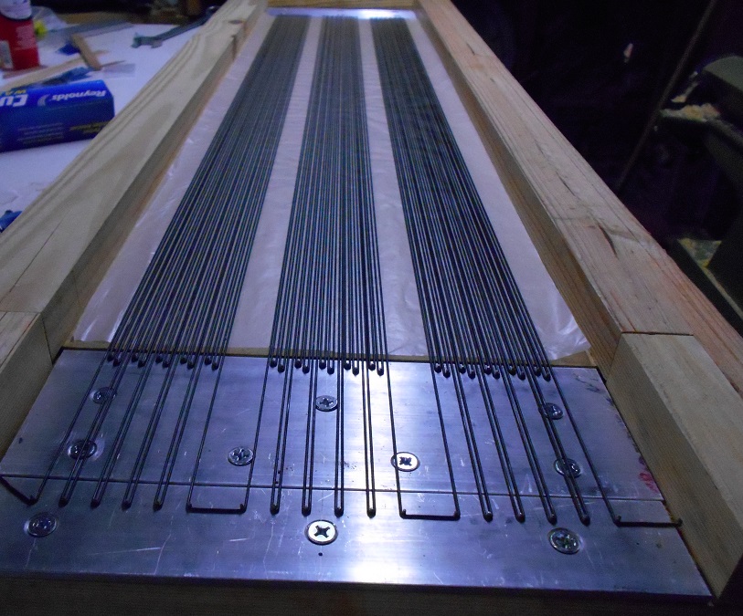
Hey yall, looks like the wire stretcher is gonna work fine.
I don't want to hijack this thread any further so I'm gonna start a new thread when I'm ready to start assembling the stators.
It's gonna take some time though... got a honey-do list a mile long and I haven't finished designing the supporting lattice yet. Just thought it would be wise to do the jig first.
30 dollar is not very cheap
Depends... if you could get exactly what you need versus having to buy a bunch of small transformers (+ shipping from Europe).
Never the less, I would expect it to be a bit more for custom built transformer versus mass produced power transformers.
Hi bengel
Done some sums on your transformer needs....
I've assumed that you want fL=250 Hz and a bandwidth of 20 kHz. The segmentation and choice of resistor for fL=250 Hz means that the panel behaves as a capacitor of about 82 pF = Cesl in formula below - this is the capacitive load presented by the ESL to the transformer at 20 kHz. I've assumed that the resonant frequency of the loaded transformer =bandwidth (it forms a second-order low pass filter).
The resonant frequency of the transformer is
fo=1/2/pi/{sqrt[(Cesl+Ct).(Lt+N^2.Lamp)]}
where:
Cesl = 82 pF
Ct = transformer capacitance to be determined
Lt = transformer leakage inductance to be determined
Lamp = amplifier output inductance
N = transformer step-up ratio
Then for:
N = 150, Lamp = 1 uH you need Lt < 110 mH and Ct < 400 pF
N = 150, Lamp = 3 uH, you need Lt < 160 mH and Ct < 195 pF
N = 150, Lamp =10 uH, you need Lt < 195 mH, and Ct < 70 pF
N = 200, Lamp = 1 uH you need Lt < 135 mH and Ct < 280 pF
N = 200, Lamp = 3 uH, you need Lt < 185 mH and Ct < 125 pF
N = 200, Lamp =10 uH, you need Lt <160 mH, and Ct < 32 pF
These are the combined specs for a pair of transformers (one each side of the HT) so each transformer should have half of the given Lt and no more than 2 x the indicated capacitance.
These are the specs for the transformers with the lowest resonant frequency that will meet your needs. Other transformers will do the job, but the requirements will not be so easy to meet.
If you use the six 15VA Talema 230p/9s transformers I discussed earlier the total inductance is Lt =96 mH and capacitance Ct=81 pF and this will work fine too. They would be better if the inductance was higher and the capacitance lower - a smaller transformer 10VA or 7VA would possibly be good. You might get away with six 20 VA 230/9 transformers, but I expect that six 50 VA transformers will be limiting.
If you use a pair of the Plitron 1:75 transformers Lt = 44 mH, Ct unknown (perhaps 80 pF) (@C$720 ouch) then they will work OK so long as the amplifier does not have a high output inductance (OK on 1 and 3 uH).
You will hopefully notice that the table of values favours transformers with a higher leakage inductance and lower capacitance, especially as the step-up ratio increases, and the amplifier inductance increases. The 15 VA transformers were 16 mH each. I've not measured 50 VA toroids, but I have measured 160 VA toroids and got Lt=2.2 mH and Ct=1.2nF they are definitely out.
Sorry I cannot tell you the exact turns, core sizes etc for a pair made to suit one of the specs. But hopefully this will help.
regards
Rod
If you use the six 15VA Talema 230p/9s transformers I discussed earlier the total inductance is Lt =96 mH and capacitance Ct=81 pF and this will work fine too. They would be better if the inductance was higher and the capacitance lower - a smaller transformer 10VA or 7VA would possibly be good. You might get away with six 20 VA 230/9 transformers, but I expect that six 50 VA transformers will be limiting.
Thanks so much for the help!
Couple of questions though... is that 6 transformers per panel? I would presume so as that gives me about 153:1 step.
Also, why not go with 230p/6s transformers? Seem like it would be better to have fewer but not sure what the consequences of have a higher step ratio would be.
I am reading thru a bunch of old threads about guys who have built their own transformers.... there is a lot to it to be sure 🙂 I am not even sure what the best core material would be (have several choices).
Hi bengel
Yes. Six 230p/9s transformers per ESL, 3 each side of HT, with all of the 9V windings in parallel, and 230V windings in series.
If I understand you correctly, you are suggesting four 230p/6s transformers to give the same step up ratio and 24 Vac rating at 200 Hz (instead of 36Vac)?
Yes that would work fine, actually better bandwidth wise. For four of the 15VA transformers Lt = 64 mH, and Ct = 65 pF. Actually, the 6V versions are more frequently on special too.
I've looked at winding transformers too - forget about winding your own toroids - > 5,000 turns with out a machine is not possible. But winding onto a bobbin for E&I or C-core is possible.
regards
Hey yall, looks like the wire stretcher is gonna work fine.
I don't want to hijack this thread any further so I'm gonna start a new thread when I'm ready to start assembling the stators.
It's gonna take some time though... got a honey-do list a mile long and I haven't finished designing the supporting lattice yet. Just thought it would be wise to do the jig first.
Hi Charlie,
The wire stretcher seems to work nicely. Congratulations!
I've looked at winding transformers too - forget about winding your own toroids - > 5,000 turns with out a machine is not possible. But winding onto a bobbin for E&I or C-core is possible.
regards
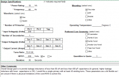
Oh no... not winding them myself 🙂. Just trying to put together a spec to have a professional transformer shop build it for me (just getting a quote).
Attached is what I got so far... (appreciate any feedback).
Attachments
Hi
If you want to keep within the transformer manufacturers normal play area, I would use a silicon-steel tape-wound toroidal core, as is normal for toroidal power transformers. You can play games with using materials with a more linear permeability for the core e.g. ferrite, but the cost is higher and there is almost nothing to be gained.
If you want the simplest and cheapest quote, I would suggest sticking with a 50 Hz 10 VA 230p/6s with a single secondary winding and buying eight of them (4 for each ESL)
Moving to transformers that operate directly at the higher voltage is not so simple and certainly takes him into a new part of the sandpit . If you want to do a pair at 1:75 step-up ratio with 60 Hz rating, then the low voltage winding needs to be 7.2V (to compensate for the slightly higher frequency) in and the high potential side must be 540V (=7.2V*75). As a secondary condition you want leakage inductance below 80 mH (I note you used uH on the sheet) and winding capacitance below 60 pF. But in my experience, transformer manufacturers are not so hot on getting the design right when you specify the impedance measurements. This is likely to more hit and miss unless your manufacturer is particularly approachable.
best wishes
Rod
Thanks for the help.... I will submit that to him and see what comes back. Good catch on the units for inductance... a typo on my part 🙂.
@ 10VA it would have a max current of 1.4 amps on the secondary. I am curious as to what kind of impedance/load this would present to my amp throughout the bandwidth (250hz to 20ish khz).... i.e. I don't want to smoke it (or more likely, trip the protection limiter).
Even if this doesn't work out at least I am learning something about ESL transformers 🙂.
Again, thanks for all the advice/help....
Hi bengel
Good question - there are a couple of factors that mitigate against high power rating for ESL transformers.
Firstly, ESLs are essentially voltage driven devices. If you work out the impedance of the segmented ESL with transformers on the front = sqrt(2.pi.f.C/R)/N^2, you find the impedance is many 10s of ohms at low frequencies where most of the signal power is (50% of audio signal power is below 500 Hz) - so there is very little power needed in the ESL itself. (note, it is the ESL load reflected back to the input that determines the current draw through the transformer.) A similar consideration applies to the power dissipated in the resistors - they have to be run very loud with a lot of high frequency content to get more than 10 watts lost in the resistors.
Secondly, the low voltage windings are in parallel - so power is shared between the different xformers.
Thirdly, a speaker with a nominal 86 dB sensitivity at 2.83 V in is quite loud if is running with 2.83 V rms input - most of the high voltage rating is required simply to cope with the peaks in the music. 10 Vrms input is usually very loud.
Fourthly, purpose built transformers ESL transformers tend to have larger cores purely to get the voltage rating up without having to wind > 10,000 turns - 100VA cores would be about right.
regards
Rod
That is great to hear!Hey yall, looks like the wire stretcher is gonna work fine... I'm gonna start a new thread when I'm ready to start assembling the stators
Will look for your new thread, am interested to hear how your crossbar gluing scheme works out.
- Home
- Loudspeakers
- Planars & Exotics
- About to take the ESL plunge