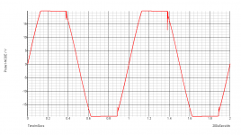
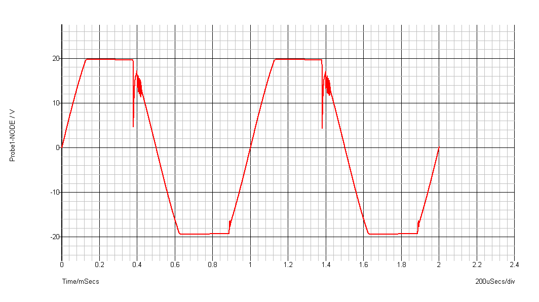
I wonder what the zeners do to full power/load distortion under clip compared to how it looks without.
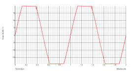
The zeners prevents rail sticking and oscillation a bit, but not very much.
The first attachment is without zener and the second is with zener.
Attachments
Helped a little only... but isn't the total resistance too high? I have seen such high resistances in such places as many times as 0 !!! 😀
Your simulator certainly produces real-looking waveforms.
😎
The zeners prevents rail sticking and oscillation a bit, but not very much.
The first attachment is without zener and the second is with zener.
Oh. What did you change that got you away from this, then?
http://www.diyaudio.com/forums/atta...about-simple-machine-simplemachine-graph3.png
Or is that just without zener at even higher drive?
I wonder what the zeners do to full power/load distortion under clip compared to how it looks without.
That was ambiguous. I meant below clip.
Your simulator certainly produces real-looking waveforms.
😎
Thanks for your post, Sir.
I use Simetrix. I don't have a scope yet. So, for now I have to believe in the software.
Pity that I won't be able to know the overload response once the amp is assembled, coz I won't run it into overload. 😀
cheers
That was ambiguous. I meant below clip.
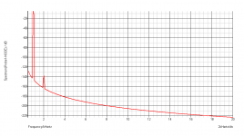
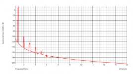
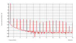
Below clip performance.
1kHz at 1V P-P, 10V P-P and 30V P-P at 8ohm.
Results are same without zeners.
Attachments
Assembled. initial listenning impression... not bad.
Simple machine is working very well. Crystal clean treble at full power into 8ohm fullrange. But the bass is a little lower in volume. But in volume only; fed from the low pass of an LR24 Xover it produced bass effortlessly. I think the circuit's bass gain is a little low. However that's no problem for me coz it will be in the high pass. 🙂 Overall sound quality is excellent. Midrange is open and transparent even at high output levels. 😎
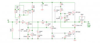
I used the following schematic, everything same except the 10nF cap and 100ohm resistor at the base of Q2. The amp was oscillating from the very first run(all FM channels DEAD). Based on my knowledge and experience I suspected Q2+Q3 being the culprit. They were. Placing those two parts cleared all annoyances and now it's One Damn Clean Amp. Anything below 10nF didn't help. In the simulator these two parts seem to lower the oscillation at clipping better than a 6V2 Zener. So I didn't use the zener in the CCS. I will not drive it even into full power so clip performance isn't a matter for me, others may care. 😉
I liked the sound, will listen to it for some days and will see if anything exciting happens. 😀 In fact I am expecting some excitement.
Some photos will be uploaded shortly.
cheers
Simple machine is working very well. Crystal clean treble at full power into 8ohm fullrange. But the bass is a little lower in volume. But in volume only; fed from the low pass of an LR24 Xover it produced bass effortlessly. I think the circuit's bass gain is a little low. However that's no problem for me coz it will be in the high pass. 🙂 Overall sound quality is excellent. Midrange is open and transparent even at high output levels. 😎
I used the following schematic, everything same except the 10nF cap and 100ohm resistor at the base of Q2. The amp was oscillating from the very first run(all FM channels DEAD). Based on my knowledge and experience I suspected Q2+Q3 being the culprit. They were. Placing those two parts cleared all annoyances and now it's One Damn Clean Amp. Anything below 10nF didn't help. In the simulator these two parts seem to lower the oscillation at clipping better than a 6V2 Zener. So I didn't use the zener in the CCS. I will not drive it even into full power so clip performance isn't a matter for me, others may care. 😉
I liked the sound, will listen to it for some days and will see if anything exciting happens. 😀 In fact I am expecting some excitement.
Some photos will be uploaded shortly.
cheers
Attachments
Last edited:
10nf, jeez, i was out by a country mile 😀 Then again looking about i'm not really surprised. In this kind of setup the source follower is likely to be a heck of a lot faster than the mosfet used as the gain stage.
Glad you sorted it & are having a listen, it appears that a simulation is now reality 😉
Bests to you shaan 🙂
Glad you sorted it & are having a listen, it appears that a simulation is now reality 😉
Bests to you shaan 🙂
Your output elcap is kind of small for best bass. Distortion goes up in a cap when a voltage is developped over it. D.Self did a bold aproach and used a 100.000 uF.
The bass distortion disappeared.
The bass distortion disappeared.
10nf, jeez, i was out by a country mile 😀 Then again looking about i'm not really surprised. In this kind of setup the source follower is likely to be a heck of a lot faster than the mosfet used as the gain stage.
Glad you sorted it & are having a listen, it appears that a simulation is now reality 😉
Bests to you shaan 🙂
It looked clean in the simulator without those two parts and my ignorance coupled by excitement did its job well... forgot this simple thing. Well, in the future I think I will try to be more careful. The circuit which worked showed me what the simulation missed/misses.
Also, there is a peculiar problem, the sound goes furrrr-furrrr if the power is turned off when there is a signal at the input. How to solve this other than using relays?
thanks.
Your output elcap is kind of small for best bass. Distortion goes up in a cap when a voltage is developped over it. D.Self did a bold aproach and used a 100.000 uF.
The bass distortion disappeared.
I will try it with some big caps within a couple of days. thanks for the info.
If you don't fancy having a relay on the output then think about something on the input instead maybe? With no music applied i assume it doesn't make this disagreeable noise 🙂Also, there is a peculiar problem, the sound goes furrrr-furrrr if the power is turned off when there is a signal at the input. How to solve this other than using relays?
Oh ya! Why not. Relays at input! Thanks man! 
But why doesn't the amp drain the caps after power off? My other se class a amp does... power down-caps empty!
But why doesn't the amp drain the caps after power off? My other se class a amp does... power down-caps empty!
Stick a high value resistor accross the output cap, anything over 10K won't put any dangerous current into the speaker if there is an offset voltage, 100K would be better but take longer to discharge. It'll discharge the large capacitor when you shut down.
I'm not sure why the cap doesn't discharge, but then i haven't seen the other circuit you are refering to 😉
Bests.
I'm not sure why the cap doesn't discharge, but then i haven't seen the other circuit you are refering to 😉
Bests.
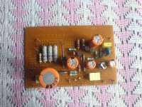
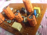
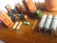
The amplifier is not gem grade. But is very good at sonix. I tried my best to get rid
of just those two stupid looking jumpers, I failed. The board didn't fail at anything. Nothing went bang in the very first run. But it oscillated until I placed a 10nF cap(the green cap near the power resistors) from base to collector and a 100ohm resistor from emitter to base(these are common knowledge with fast CCS I know).
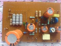
Once the two components are placed, the circuit is a piece of beauty... sonically. Have run to full power... for hours with no sign of any problem. Very detailed sound from bass right up to the extremes. Iq stable at 2.21A with no input. Power supply is 40V Tranny+4700uF+Cap Multiplier+1000uF(not good enought 😉).
btw, The bass matter has been solved. It was that 0.47nF yellow box. I installed a 10uF (as in the schematic) electrolytic today and now it shakes the doors well... I can hear the door. 😀
I was out of 1K and 270ohm 1/4watt resistors so used 1/2watt things. This brought some beauty for the eyes. For the ears, I don't know. Also I was out of 0.1uF things so used multiple1 0.047uF caps wherever needed. Looking at the board, I have this thought several times that the arrangement is too compact for a class-A amp. Placing my finger over the BJTs I found out that they weren't as hot as I expected them to be. The 1K resistor near the power resistors is connected from output capacitor's -ve leg(the output) to ground.
Once again, the amp produces exceptionally good sonics with any kind of program material. Plus I felt the sound to be less "sweet" and more "accurate"... exactly opposite to my previous se class-a amp. And at full volume It is way more louder than that. All effort and time very well spent. I will be making another board soon and will update here.
Nothing critical was found on parts placement as was expected. I tried to place them on the board as they appear in their position in the schematic. I think this has left me with those two jumpers. I wanted to finish it as soon as possible. 😉
Have you people made this kind of amps? If you haven't then you can try it. It is a fine amplifier to own and listen. Of course its specs are somewhat lacking compared to the more exotic machines and also it runs hot as hell, but I think you too will like the wide, dynamic and crystal clean music it brings. I have run my average and cheap fullrange (not so full the range, highs usually doesn't sing good through it) with it and the speaker sounds like no speaker, enough... you already know what I mean.
Cheers!
of just those two stupid looking jumpers, I failed. The board didn't fail at anything. Nothing went bang in the very first run. But it oscillated until I placed a 10nF cap(the green cap near the power resistors) from base to collector and a 100ohm resistor from emitter to base(these are common knowledge with fast CCS I know).
Once the two components are placed, the circuit is a piece of beauty... sonically. Have run to full power... for hours with no sign of any problem. Very detailed sound from bass right up to the extremes. Iq stable at 2.21A with no input. Power supply is 40V Tranny+4700uF+Cap Multiplier+1000uF(not good enought 😉).
btw, The bass matter has been solved. It was that 0.47nF yellow box. I installed a 10uF (as in the schematic) electrolytic today and now it shakes the doors well... I can hear the door. 😀
I was out of 1K and 270ohm 1/4watt resistors so used 1/2watt things. This brought some beauty for the eyes. For the ears, I don't know. Also I was out of 0.1uF things so used multiple1 0.047uF caps wherever needed. Looking at the board, I have this thought several times that the arrangement is too compact for a class-A amp. Placing my finger over the BJTs I found out that they weren't as hot as I expected them to be. The 1K resistor near the power resistors is connected from output capacitor's -ve leg(the output) to ground.
Once again, the amp produces exceptionally good sonics with any kind of program material. Plus I felt the sound to be less "sweet" and more "accurate"... exactly opposite to my previous se class-a amp. And at full volume It is way more louder than that. All effort and time very well spent. I will be making another board soon and will update here.
Nothing critical was found on parts placement as was expected. I tried to place them on the board as they appear in their position in the schematic. I think this has left me with those two jumpers. I wanted to finish it as soon as possible. 😉
Have you people made this kind of amps? If you haven't then you can try it. It is a fine amplifier to own and listen. Of course its specs are somewhat lacking compared to the more exotic machines and also it runs hot as hell, but I think you too will like the wide, dynamic and crystal clean music it brings. I have run my average and cheap fullrange (not so full the range, highs usually doesn't sing good through it) with it and the speaker sounds like no speaker, enough... you already know what I mean.
Cheers!
Attachments
I made similar amplifier long time ago, but with BJTs, and I wonder it will sound be similar with FETs, I must try for curiosity.
Regards
Regards
I see i'm not the only one who builds with veroboard around here 😉
Nice to hear you are enjoying your amp shaan 🙂 Must be one of the fastest builds on here 😀
Enjoy!
Bests, Mark.
Nice to hear you are enjoying your amp shaan 🙂 Must be one of the fastest builds on here 😀
Enjoy!
Bests, Mark.
- Status
- Not open for further replies.
- Home
- Amplifiers
- Solid State
- About This "Simple Machine"