I am trying to find good PCB making kits here. I have made many dot board designs on many amp schematics and now I need a break, may be an upgrade 😉. Eventually I will become a PCB guy too! 😀
Congrats Shaan.
Which transistor are you speaking about?
What is the purpose of the 1K resistor at the output?
But it oscillated until I placed a 10nF cap(the green cap near the power resistors) from base to collector and a 100ohm resistor from emitter to base(these are common knowledge with fast CCS I know).
Which transistor are you speaking about?
What is the purpose of the 1K resistor at the output?
shaan is refering to the constant current, the upper mosfet which was oscillating just a tad when the amp came out of clipping.
I should imagine that the 1K resistor is there to charge the output capacitors in the event of there being no loudspeaker connected at switch on.
Bests.
I should imagine that the 1K resistor is there to charge the output capacitors in the event of there being no loudspeaker connected at switch on.
Bests.
Congrats Shaan.
Which transistor are you speaking about?
Q2. The BC550C near the upper MOSFET. See schematic below.
What is the purpose of the 1K resistor at the output?
Exactly what event horizon said. 😉 😀
Attachments
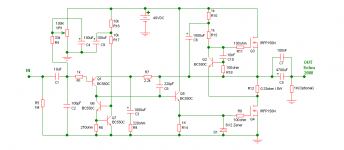
The original was just a random experiment of mine with the Zen amp. Some knowledge and experience based design. Throughout the thread many has suggested interesting ways to upgrade it. I did whatever I found possible and practical. And after a while the final circuit was born. The addition of the emitter follower is a mentionable step. Credits to event horizon for the info on this.
Initially it was done in simulator. Based on the test results of the simulator I built it and the only problem I had to face in the real world is an oscillating CCS, which was easily solved by a resistor and a small capacitor. Simple machine, simple problem, simple solution. It sounds simple too, simple and free, no stress, ringing or overshoot! 😀
cheers
Last edited:
Buy a decent soundcard and a measurement programm and measure it directly.
100,-$ should buy you that.
100,-$ should buy you that.
I've got a good soundcard. Can you please suggest any good freeware measuring program?
Thanks/(sorry i removed the post thinking it is lame, apologies)
Thanks/(sorry i removed the post thinking it is lame, apologies)
i use Audiotester at home. It costs 39,-€ in the full version. The free version terminates after 10 minutes and you can go back to measurement with he stored values immediately. I am not sure if there are english instructions though.
The advantage of direct measurements is that it gives you the spectrum that is extremely important for sound. A simple THD analysys does not tell you much.
ARTA has a free version too but i do not know if it is any good for electronics measurements. Rightmark Analyser ?
The advantage of direct measurements is that it gives you the spectrum that is extremely important for sound. A simple THD analysys does not tell you much.
ARTA has a free version too but i do not know if it is any good for electronics measurements. Rightmark Analyser ?
Tell me how you like it. I find it very intuitive. Start with the 2 dimensional FFT if you want quick results.
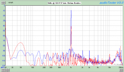
Some ameteur tests...
Today I installed the audiotester and ran these tests on the simple machine. It took quite a while for me to become friendly with the interface. I usually use trueRTA which recently is crashing a lot. I think it's time to set it free 😀.
I tested it upto 12V P-P and will try to upload graphs of higher output voltages later. The results look promising, as expected, I already felt the sound to be "clean" than "sweet".
misc- Looking at the noise floor I think it's time for me to buy a better sound card. 😱
Cheers
Attachments

Last edited:
Is a soudcard able to measure a good amp?
It depends on the souncard and how low you want to go with the THD.
Current AD on souncards have become pretty good - its not like the time of the sound blaster anymore.
Check the EMU1616.

See the measurements of the EMU 0202 USB on the Liberty Instruments, Inc. Home Page page.
I have an e-magic card where i can maesure down to -120dB but only with 48kHz sampling. I think a modern relatively cheep soundcard is a lot better then most power amplifiers. When you have a labtop with battery supply, measurements get often much claener when not using the PSU into the wall oulet.
I have an e-magic card where i can maesure down to -120dB but only with 48kHz sampling. I think a modern relatively cheep soundcard is a lot better then most power amplifiers. When you have a labtop with battery supply, measurements get often much claener when not using the PSU into the wall oulet.
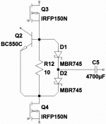
I'm surprised you test R12 both under and over the load,
yet never occoured to you to split R12 in half? With load
and NFB tied to the midpoint? Both halves work opposite
equally, and can drive twice current swing into the load.
But this arrangement is only valid for true Class A.
The next advancement over Split R12 is to span unsplit
R12 with series pair of Schottky diodes. Tie Load and NFB
to midpoint of Schottkys, but tie no load directly to R12!
Now R12 only provides a reserve current leak that keeps
anything else but Schottkys from accidently turning off.
Capable of extremely smooth AB crossing. Really: Class
VischB (Square Law Schottky Diodes) + CCS (R12).
The bootstarp is a good idea, but Cordell warns 1500pF
extra Miller CDG when VDS is less than VGS. I take this
to mean: You may need a lot more current in the strap
to be effective, regardless what the simulation sais.
Attachments
Last edited:
Probably it will be interesting to look atI recently assembled this amp and it is running good....
http://www.diyaudio.com/forums/solid-state/99313-ab-dynamic.html
- Status
- Not open for further replies.
- Home
- Amplifiers
- Solid State
- About This "Simple Machine"