I should imagine that's simply down to the lower resistance value.
Now try replacing R6 with a simple constant current. An NPN transistor, two diodes & a resistor will give you a good idea to see if it's worth persuing. again connect from the base of the transistor to the +ve rail. I'd suggest a resistor of about 270R to set the CC. This will result in about 2.7mA continuous through the input transistor collector.
It should speed things up & result in lower distortion yet again.
I wish i could sim things this quickly lol 🙂
Of course 🙂 I think you'll see something else before that though, i'm just gathering stuff together (including test gear) for a new project that will be turned into a thread on here when i get it all together.
Bests, Mark.
Yes it did!!! And now it's flying supersonic! 😀
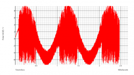
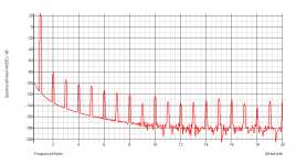
Severe oscillation!
Anti-oscillation medicines please!
Thanks.
Attachments
Last edited:
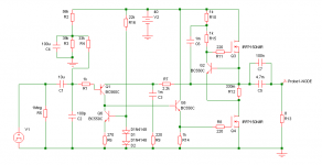
Ah, yes, i expected this as there is no compensation. Miller cap from collector of the CC to the output. Try the usual 100pf & go from there 😉 Effectively your output stage is the VAS so it shouldn't be a problem.
Ah, yes, i expected this as there is no compensation. Miller cap from collector of the CC to the output. Try the usual 100pf & go from there 😉 Effectively your output stage is the VAS so it shouldn't be a problem.
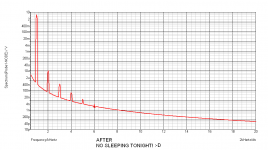
THANKS Doctor! That small 100pF brown tablet with two wires was a wonderful medicine! God bless you!
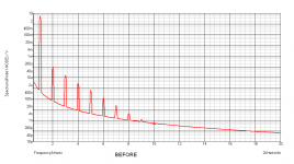
Besides this, the figures are clearly a lot better than before. Hmmmm... I already slept too much in the daytime today...
I mean, where I started and where I am! 😀 😎 Thanks for the great suggestions!
BTW, I replaced the diodes with a BJT (just because I read somewhere that it is better is some ways 😉 )
Attachments
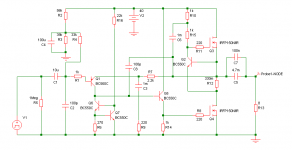
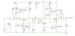
That's cool & better 😉 The only thing you have added that is really in the circuit is the emitter follower, the rest are just a change from a resistor to an active load (the constant current).BTW, I replaced the diodes with a BJT (just because I read somewhere that it is better is some ways 😉 )
As you say, the dual transistor CC is better, i agree, yet it can be improved & again nothing will be in the audio circuit. Try splitting the resistor from the base of the CC to the positive rail in two. Then connect a capacitor from the junctions of the new two part resistor to the negative rail (10uf). This will increase PSRR & again might help lower distortion.
Don't forget to play with the value of the miller cap 😀
I think i'm enjoying this as much as you 🙂
Bests, Mark. Who is probably off to watch a blu ray & get hammered

That's cool & better 😉 The only thing you have added that is really in the circuit is the emitter follower, the rest are just a change from a resistor to an active load (the constant current).
As you say, the dual transistor CC is better, i agree, yet it can be improved & again nothing will be in the audio circuit. Try splitting the resistor from the base of the CC to the positive rail in two. Then connect a capacitor from the junctions of the new two part resistor to the negative rail (10uf). This will increase PSRR & again might help lower distortion.
Don't forget to play with the value of the miller cap 😀
I think i'm enjoying this as much as you 🙂
Bests, Mark. Who is probably off to watch a blu ray & get hammered
Possibilities seem endless! Whatever, I am gonna try this too...
Thanks!
Some more things...
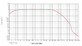
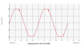
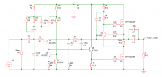
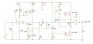
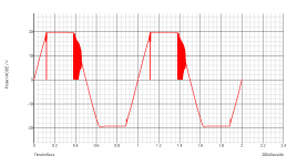
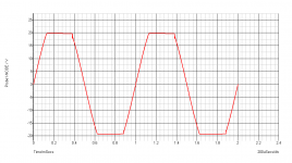
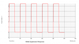
Bandwidth and Clipping graph with 100pF and 470pF Miller cap. I'm getting hell tickled!
Bandwidth and Clipping graph with 100pF and 470pF Miller cap. I'm getting hell tickled!
Attachments
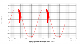
Hi shaan, it looks to me like the constant current is a little on the fast side which is what's causing the rather large oscillation with the 100pf miller cap.
Try putting a 100 - 270R resistor from the base Q2 to the current control resistor R12. The transistor will then slow it's transitions from on to off etc, if it doesn't have a lot of effect then try a small capacitor from base to collector on Q2. Something along the lines of 1nf or smaller (maybe the same kind of value as the miller cap might do). I'm sure you'll soon get it much more stable 😀
Try putting a 100 - 270R resistor from the base Q2 to the current control resistor R12. The transistor will then slow it's transitions from on to off etc, if it doesn't have a lot of effect then try a small capacitor from base to collector on Q2. Something along the lines of 1nf or smaller (maybe the same kind of value as the miller cap might do). I'm sure you'll soon get it much more stable 😀
Hi shaan, it looks to me like the constant current is a little on the fast side which is what's causing the rather large oscillation with the 100pf miller cap.
Try putting a 100 - 270R resistor from the base Q2 to the current control resistor R12. The transistor will then slow it's transitions from on to off etc, if it doesn't have a lot of effect then try a small capacitor from base to collector on Q2. Something along the lines of 1nf or smaller (maybe the same kind of value as the miller cap might do). I'm sure you'll soon get it much more stable 😀
Neither helped! 🙁
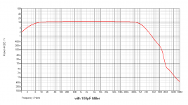
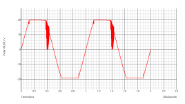
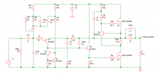
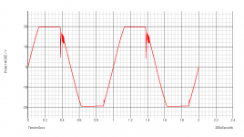
However, putting a 330pF Miller helps a lot and am gonna be with this. Have a look on the schematics and their graphs. As I have no intention to run the amp to clipping I am happy with this. 😉
Also today I bought all the parts and am gonna start assembling it now. I will update once it is finished. As the final circuit is fairly complex and far different and larger than the initial one, I thought I'd make this one on a new dot board; only to find out that I am out of boards. And after sometime I found that I am out of solder too!!! So it was postponed until today! 😀
cheers...
Attachments
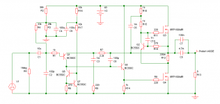
Ok, try changing the chain of resistors on the bootstrap from 1K each to 10K each. That should definately have an effect, let us know what happens 😉Neither helped! 🙁
for you
Helped a little only... but isn't the total resistance too high? I have seen such high resistances in such places as many times as 0 !!! 😀
I think the 330pF approach is better so I will go with that.
Ok, try changing the chain of resistors on the bootstrap from 1K each to 10K each. That should definately have an effect, let us know what happens 😉
Helped a little only... but isn't the total resistance too high? I have seen such high resistances in such places as many times as 0 !!! 😀
I think the 330pF approach is better so I will go with that.
Attachments
No worries, go with how you feel about it 🙂I think the 330pF approach is better so I will go with that.
No worries, it keeps me in practice 😀 Don't want the grey matter solidifying just yet 😉Thanks a lot for all the help.
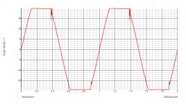
I suspect the gate-source voltage of the output devices shoots very high during clipping. If this was limited, perhaps it would help with the oscillation and sticking?
The easiest way to do this (maybe not the cleanest) is with zeners - one between ground and the base of Q5, the other between the source of Q3 and collector of Q2.
You would have to experiment to find the best zener voltages - high enough to not restrict output current, but not too high. I would guess about 5.6V.
I suspect the gate-source voltage of the output devices shoots very high during clipping. If this was limited, perhaps it would help with the oscillation and sticking?
The easiest way to do this (maybe not the cleanest) is with zeners - one between ground and the base of Q5, the other between the source of Q3 and collector of Q2.
You would have to experiment to find the best zener voltages - high enough to not restrict output current, but not too high. I would guess about 5.6V.
Hmmm... This I think I will keep in mind... very small(and usual) addition, but it will probably work, plus the Miller cap is now 220pF from 330pF.
hopefullyfullofhope! 😀
Thanks.
.
Attachments
It looks like you drastically changed some switching response of Q2 with those zeners. Maybe looking at limiting its linear range more directly somehow would help further. Maybe some emitter resistance. If it helps but you need more base drive maybe you could put some source resistance on Q3.
Last edited:
I wonder what the zeners do to full power/load distortion under clip compared to how it looks without.
- Status
- Not open for further replies.
- Home
- Amplifiers
- Solid State
- About This "Simple Machine"