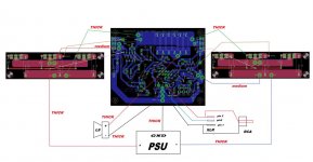
just look at PCB screenshot in #49
then look at schm in same post and , I hope , everything will be clear
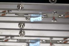
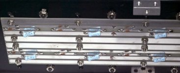
in other words - there is group of 6pcs 0R27 resistors connected to output node
in that group , mount just two of them , R31 and R32 for instance
rest (4 pcs) is intended when using multiple outputs on daughter-boards
then look at schm in same post and , I hope , everything will be clear
in other words - there is group of 6pcs 0R27 resistors connected to output node
in that group , mount just two of them , R31 and R32 for instance
rest (4 pcs) is intended when using multiple outputs on daughter-boards
Someone asked for list of parts , basic version
so , here it is - generated by Eagle
for one channel , no detailed dimensions , sorry (read previous posts regarding voltages etc.)
that would be too much of spoon-feeding ....... in fact , everybody knows that proper amp making procedure is having pcbs in hands , thinking about parts and where to buy them ..... then waiting for parts to arrive while working on rest of hardware .....

so:
** marked what's included in kit with pcbs
LIST IS FOR ONE CHANNEL !
Part Value Device Package Description
C1 3u3 CPOL-EUE5-5 E5-5 POLARIZED CAPACITOR, European symbol
C2 22u CPOL-EUE3.5-8 E3,5-8 POLARIZED CAPACITOR, European symbol
C3 1u C-EU050-050X075 C050-050X075 CAPACITOR, European symbol
C4 470u CPOL-EUE5-13 E5-13 POLARIZED CAPACITOR, European symbol
C5 6p8 C5/2.5 C5B2.5 CAPACITOR
**C6 1u MKC C-EU150-064X183 C150-064X183 CAPACITOR, European symbol
C7 470u CPOL-EUE5-13 E5-13 POLARIZED CAPACITOR, European symbol
C8 470u CPOL-EUE5-13 E5-13 POLARIZED CAPACITOR, European symbol
C9 470u CPOL-EUE5-13 E5-13 POLARIZED CAPACITOR, European symbol
C10 1u C-EU050-050X075 C050-050X075 CAPACITOR, European symbol
C11 1u C-EU050-050X075 C050-050X075 CAPACITOR, European symbol
D1 1N4148 1N4148DO35-7 DO35-7 DIODE
LED1 green LED3MM LED3MM LED
LED2 green LED3MM LED3MM LED
LED3 green LED3MM LED3MM LED
LED4 green LED3MM LED3MM LED
LED5 green LED3MM LED3MM LED
LED6 green LED3MM LED3MM LED
**Q1 J271 2N38202SJ74BL TO92L P-Channel Junction FET
**Q2 BC556C -PNP-TO92L TO92L PNP Transistror
**Q3 MMBF5486 SST5484BOTTOM548 SOT23 N-Channel JFETs
Q4 BD140-16 BD140 TO126AV PNP TRANSISTOR
**Q5 BC556 -PNP-TO92L TO92L PNP Transistror
**Q6 BC556C -PNP-TO92L TO92L PNP Transistror
**Q7 J271 2N38202SJ74BL TO92L P-Channel Junction FET
**Q8 BC546C -NPN-TO92L TO92L NPN Transistror
**Q9 BC546C -NPN-TO92L TO92L NPN Transistror
Q10 IRFP150 IRFP150 TO247BV HEXFET Power MosFet
Q11 IRFP150 IRFP150 TO247BV HEXFET Power MosFet
R1 22K R-EU_0207/10 0207/10 RESISTOR, European symbol
R2 22K R-EU_0207/10 0207/10 RESISTOR, European symbol
R3 2M2 R-EU_0207/10 0207/10 RESISTOR, European symbol
R4 220K R-EU_0207/10 0207/10 RESISTOR, European symbol
R5 33 R-EU_0207/10 0207/10 RESISTOR, European symbol
R6 4R7 R-EU_0207/10 0207/10 RESISTOR, European symbol
R7 680 R-EU_0207/10 0207/10 RESISTOR, European symbol
R8 33 R-EU_0207/10 0207/10 RESISTOR, European symbol
R9 220 R-EU_0207/10 0207/10 RESISTOR, European symbol
R10 47 R-EU_0207/10 0207/10 RESISTOR, European symbol
R11 1K R-EU_0207/10 0207/10 RESISTOR, European symbol
R12 820 R-EU_0207/10 0207/10 RESISTOR, European symbol
R13 300 to 330 R-EU_0207/10 0207/10 RESISTOR, European symbol
R14 33 R-EU_0207/10 0207/10 RESISTOR, European symbol
R15 4R7 R-EU_0207/10 0207/10 RESISTOR, European symbol
R16 33 R-EU_0207/10 0207/10 RESISTOR, European symbol
R17 5K1 R-EU_0207/10 0207/10 RESISTOR, European symbol
R18 5K1 R-EU_0207/10 0207/10 RESISTOR, European symbol
R19 100 R-EU_0207/10 0207/10 RESISTOR, European symbol
R20 220K R-EU_0207/10 0207/10 RESISTOR, European symbol
R21 220 R-EU_0207/10 0207/10 RESISTOR, European symbol
R22 1K5 R-EU_0207/10 0207/10 RESISTOR, European symbol
R23 1K5 R-EU_0207/10 0207/10 RESISTOR, European symbol
R24 82K R-EU_0207/10 0207/10 RESISTOR, European symbol
R25 1K R-EU_0207/10 0207/10 RESISTOR, European symbol
R26 180 R-EU_0207/15 0207/15 RESISTOR, European symbol
R27 180 R-EU_0207/12 0207/12 RESISTOR, European symbol
R28 1K R-EU_0207/10 0207/10 RESISTOR, European symbol
R29 0R27/3W R-EU_0617/22 0617/22 RESISTOR, European symbol
R30 0R27/3W R-EU_0617/22 0617/22 RESISTOR, European symbol
R31 0R27/3W R-EU_0617/22 0617/22 RESISTOR, European symbol
R32 0R27/3W R-EU_0617/22 0617/22 RESISTOR, European symbol
TP1 500 TRIM_EU-B64Y B64Y POTENTIOMETER
TP2 50 TRIM_EU-B64Y B64Y POTENTIOMETER
TP3 50K TRIM_EU-B64Y B64Y POTENTIOMETER
ZD5V1 ZTE ZTE DO35Z10 Z DIODE
so , here it is - generated by Eagle
for one channel , no detailed dimensions , sorry (read previous posts regarding voltages etc.)
that would be too much of spoon-feeding ....... in fact , everybody knows that proper amp making procedure is having pcbs in hands , thinking about parts and where to buy them ..... then waiting for parts to arrive while working on rest of hardware .....
so:
** marked what's included in kit with pcbs
LIST IS FOR ONE CHANNEL !
Part Value Device Package Description
C1 3u3 CPOL-EUE5-5 E5-5 POLARIZED CAPACITOR, European symbol
C2 22u CPOL-EUE3.5-8 E3,5-8 POLARIZED CAPACITOR, European symbol
C3 1u C-EU050-050X075 C050-050X075 CAPACITOR, European symbol
C4 470u CPOL-EUE5-13 E5-13 POLARIZED CAPACITOR, European symbol
C5 6p8 C5/2.5 C5B2.5 CAPACITOR
**C6 1u MKC C-EU150-064X183 C150-064X183 CAPACITOR, European symbol
C7 470u CPOL-EUE5-13 E5-13 POLARIZED CAPACITOR, European symbol
C8 470u CPOL-EUE5-13 E5-13 POLARIZED CAPACITOR, European symbol
C9 470u CPOL-EUE5-13 E5-13 POLARIZED CAPACITOR, European symbol
C10 1u C-EU050-050X075 C050-050X075 CAPACITOR, European symbol
C11 1u C-EU050-050X075 C050-050X075 CAPACITOR, European symbol
D1 1N4148 1N4148DO35-7 DO35-7 DIODE
LED1 green LED3MM LED3MM LED
LED2 green LED3MM LED3MM LED
LED3 green LED3MM LED3MM LED
LED4 green LED3MM LED3MM LED
LED5 green LED3MM LED3MM LED
LED6 green LED3MM LED3MM LED
**Q1 J271 2N38202SJ74BL TO92L P-Channel Junction FET
**Q2 BC556C -PNP-TO92L TO92L PNP Transistror
**Q3 MMBF5486 SST5484BOTTOM548 SOT23 N-Channel JFETs
Q4 BD140-16 BD140 TO126AV PNP TRANSISTOR
**Q5 BC556 -PNP-TO92L TO92L PNP Transistror
**Q6 BC556C -PNP-TO92L TO92L PNP Transistror
**Q7 J271 2N38202SJ74BL TO92L P-Channel Junction FET
**Q8 BC546C -NPN-TO92L TO92L NPN Transistror
**Q9 BC546C -NPN-TO92L TO92L NPN Transistror
Q10 IRFP150 IRFP150 TO247BV HEXFET Power MosFet
Q11 IRFP150 IRFP150 TO247BV HEXFET Power MosFet
R1 22K R-EU_0207/10 0207/10 RESISTOR, European symbol
R2 22K R-EU_0207/10 0207/10 RESISTOR, European symbol
R3 2M2 R-EU_0207/10 0207/10 RESISTOR, European symbol
R4 220K R-EU_0207/10 0207/10 RESISTOR, European symbol
R5 33 R-EU_0207/10 0207/10 RESISTOR, European symbol
R6 4R7 R-EU_0207/10 0207/10 RESISTOR, European symbol
R7 680 R-EU_0207/10 0207/10 RESISTOR, European symbol
R8 33 R-EU_0207/10 0207/10 RESISTOR, European symbol
R9 220 R-EU_0207/10 0207/10 RESISTOR, European symbol
R10 47 R-EU_0207/10 0207/10 RESISTOR, European symbol
R11 1K R-EU_0207/10 0207/10 RESISTOR, European symbol
R12 820 R-EU_0207/10 0207/10 RESISTOR, European symbol
R13 300 to 330 R-EU_0207/10 0207/10 RESISTOR, European symbol
R14 33 R-EU_0207/10 0207/10 RESISTOR, European symbol
R15 4R7 R-EU_0207/10 0207/10 RESISTOR, European symbol
R16 33 R-EU_0207/10 0207/10 RESISTOR, European symbol
R17 5K1 R-EU_0207/10 0207/10 RESISTOR, European symbol
R18 5K1 R-EU_0207/10 0207/10 RESISTOR, European symbol
R19 100 R-EU_0207/10 0207/10 RESISTOR, European symbol
R20 220K R-EU_0207/10 0207/10 RESISTOR, European symbol
R21 220 R-EU_0207/10 0207/10 RESISTOR, European symbol
R22 1K5 R-EU_0207/10 0207/10 RESISTOR, European symbol
R23 1K5 R-EU_0207/10 0207/10 RESISTOR, European symbol
R24 82K R-EU_0207/10 0207/10 RESISTOR, European symbol
R25 1K R-EU_0207/10 0207/10 RESISTOR, European symbol
R26 180 R-EU_0207/15 0207/15 RESISTOR, European symbol
R27 180 R-EU_0207/12 0207/12 RESISTOR, European symbol
R28 1K R-EU_0207/10 0207/10 RESISTOR, European symbol
R29 0R27/3W R-EU_0617/22 0617/22 RESISTOR, European symbol
R30 0R27/3W R-EU_0617/22 0617/22 RESISTOR, European symbol
R31 0R27/3W R-EU_0617/22 0617/22 RESISTOR, European symbol
R32 0R27/3W R-EU_0617/22 0617/22 RESISTOR, European symbol
TP1 500 TRIM_EU-B64Y B64Y POTENTIOMETER
TP2 50 TRIM_EU-B64Y B64Y POTENTIOMETER
TP3 50K TRIM_EU-B64Y B64Y POTENTIOMETER
ZD5V1 ZTE ZTE DO35Z10 Z DIODE
Hi, I would like to try the babelfish J adventure , but I am novice in electronics. Experts of the DIY could agree a few their times and their knowledges to make well this project?
bim
bim
damn .... wakoo Serb reading English written by Frenchie

if you are asking for (future) help , then yes
this forum is good in those things ....... as long you're doing your homework , help is always indefinitive
if you are asking for (future) help , then yes
this forum is good in those things ....... as long you're doing your homework , help is always indefinitive
 !!!!!
!!!!!not easy , but highly beneficiary ....... plenty of hard work to be as my Yoda (Manu , my own personal Froggie )
he's speaking German same as his native French and he's pretty fluent in English .... always willing to read , learn and think
so - more languages you know ........ your head is bigger

he's speaking German same as his native French and he's pretty fluent in English .... always willing to read , learn and think
so - more languages you know ........ your head is bigger
Maybe Babelfish JX?
OK
I have sort of sorted iteration with these few characteristics :
- IRFP150 outputs , quantity - read later
-good servo (OP + optocoupler based ) , not exactly cure for cancer edition , but covering good range of Iq and rails voltages ; if going much south or west, change of Rs and output resistors values is a must for optimization
-arbitrary setting of H2 ....... if you like no H2 .... and up to H2 arbitrary higher than H3
outputs , quantity , Iq and output power ;
minimal amount is 1pc of IRFP150 per quadrant , but two is preferable ; considering most likely usage of already made daughter boards for Babelfish J (V2) - that would be 2/quadrant as minimum (one bare place on daughter board) or 3/quadrant*
*reminder - that would be same as 6pcs of IRFP240/quadrant ; for further expl. read later red note
dissipation vs. power ;
considering usual/basic FW/PL rail voltage of 18Vac->21.5Vdc , minimal total Iq would be 4A (1pc IRFP150/quadrant as minimum), giving around 43Wrms/8r of non clipped output ; output is limited by current , not voltage , in this case; dissipation - 21V5 x 2 x 4A =170W , losses plus ; all that speaking of one channel .
that would be still in real FW spirit with some pluses - amp with still reasonable dissipation (even if already in monoblock realm) , somewhat higher output , SUSY blessings , yet having H2 setting possibility .
going higher - double total Iq (dissipation doubled too ) (2 or 3pcs of IRFP150/quadrant ) , giving nice and round 100Wrms/8R of non clipped output ; this time voltage and current limitations are gong hand by hand ; all that again speaking of one channel .
for my taste - that would be going out of FW spirit , leaning towards PL ("more commercial" ) approach , where usage of (argh!) less sensitive speakers is dictating need for more power.
personally -I'm always leaning towards speakers first approach - find most sensitive (note - different meaning than efficient) speakers and then make adequate powered amplifier .... that resulting in fact that I'm needing no more than weakest FW amp .......
note - you can use IRFP240 , but double minimum number vs. declamation for IRFP150
for lower Iq iteration - you can use IRFP240 and fill 2 or 3 places per daughter boards (with adequate Rs value) , for higher Iq iteration , use IRFP150 (with adequate Rs value)
now I have all that only in simulator but , taking some experience in account , I can trust it
in case that there is interest/demand , I can proceed to prototyping ;
I'm leaning to base pcb (input/drive/bias) + 4pcs of daughter boards concept ; that would be most versatile , covering every possible heatsink arrangement .
going to DiyA UMS is nice , but not in real DIY spirit - where dumpster diving is usual thing , resulting in waste range of physical arrangements for case and heatsinking
Last edited:
not easy , but highly beneficiary ....... plenty of hard work to be as my Yoda (Manu , my own personal Froggie )
he's speaking German same as his native French and he's pretty fluent in English .... always willing to read , learn and think
so - more languages you know ........ your head is bigger
The greater the odds, the greater the chalenge....
Manu
considering usual/basic FW/PL rail voltage of 18Vac->21.5Vdc , minimal total Iq would be 4A (1pc IRFP150/quadrant as minimum), giving around 43Wrms/8r of non clipped output ; output is limited by current , not voltage , in this case; dissipation - 21V5 x 2 x 4A =170W , losses plus ; all that speaking of one channel .
that would be still in real FW spirit with some pluses - amp with still reasonable dissipation (even if already in monoblock realm) , somewhat higher output , SUSY blessings , yet having H2 setting possibility .
in case that there is interest/demand , I can proceed to prototyping ;
I'm leaning to base pcb (input/drive/bias) + 4pcs of daughter boards concept ; that would be most versatile , covering every possible heatsink arrangement .
Consider me interested 😀
@ Magura
Metalkiddoe and Mighty ZM are ......... just naive and greedy kids , comparing to Yoda
for us , he is Master of Intelligence and Hedonism

edit: though ...... my head is still growing ........
Metalkiddoe and Mighty ZM are ......... just naive and greedy kids , comparing to Yoda
for us , he is Master of Intelligence and Hedonism
edit: though ...... my head is still growing ........
Attachments

Last edited:
....and I accept this challange 😀
Magura 🙂
That makes us two! Interested. I think I will take a longer route with IRFP240s in TO3 package.😛
You quoted me at the top of your posting so it seems as if I am the "agent provocateur".
I am interested and, like Dennis, I also have unfinished business with the Aleph-X. It is time to settle it.

I am interested and, like Dennis, I also have unfinished business with the Aleph-X. It is time to settle it.
In spite of the efforts I do not manage to follow you😕
just ignore everything not related to Babelfish J (V2) , which is original interest of this very thread 😉
and ...... with time , you'll learn that nothing is really off topic in this corner of Diyaudio
Attachments
- Home
- Amplifiers
- Pass Labs
- About possible Babelfish J interest