choose cheaper ones

and - for greenie a pop (and less) , buy them in quantity
funny and handy to have few bars in drawer , for future gadgets
and - for greenie a pop (and less) , buy them in quantity
funny and handy to have few bars in drawer , for future gadgets

you didn't
ZM is notorious for not making and hating BOMs
when making something , I'm always making mine own from schm and pcb directly

will post tonight/tomorrow two sets of schematics , along with wiring tips - just base pcb (pair of mosfets) and base pcb + daughter boards (up to 3 pairs of mosfets)
ZM is notorious for not making and hating BOMs
when making something , I'm always making mine own from schm and pcb directly
will post tonight/tomorrow two sets of schematics , along with wiring tips - just base pcb (pair of mosfets) and base pcb + daughter boards (up to 3 pairs of mosfets)
My kit arrived in the U.S. Friday, I was there to open today, all looks fine. thanks ZM!
I have some projects in front of it, but will watch others builds, and plan mine further.
I have some projects in front of it, but will watch others builds, and plan mine further.
Base pcb iteration - up to so-so normal rails
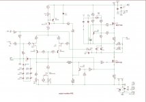
so , just base pcb and pair of IRFP150 mosfets for output
schematic and screenshot of pcb attached ; sch cleaned from some Eagle necessary clutter
observe pics in posts #35 and #36
populate pcbs as usual , all resistors are garden variety MF small jobbies except big 0R27 ones - use either Panasonic MOX 3W or square whitish 5W wirewounds
for these - mount just two pcs in group of 6 pcs
for all 0R27s - use 6-8mm risers between resistor body and pcb during soldering , to ensure good ventilation and prevent pcb heating in exploatation
prior to soldering on pcb - be sure that all multiturn pots are in mid position - confirm that with ohmmeter
wire as any of FW amps , input RCA isolated from chassis , use tiniest wire for input signal - twisted pair is preferable to coax
again , FW PSU style used - with these parts values you're good up to +/-30Vdc - take care to not exceed 50W dissipation per mosfet , under condition that you don't have more than 50C on heatsink , even in summer time
main gnd bus from PSU to pcb , then from pcb to speaker negative output
post
powering up - connect everything , ground inputs , no load on output
power up ;
if green LEDs are lit , that means two things - you mount them all as needed..... and there is proper biasing voltage for LTP cascodes 😉
- check voltage across R11 - set 10V there with TP2 and we'll have 10mA through input LTP
-check voltage across R29 ; 540mV will inform as of 2A Iq ; use less if you want ; correct with TP3 if needed
- check voltage at output node - chase 0V ( up to 30mV is OK , + or - , irrelevant) , correct with TP1
last two steps are somewhat inter-dependable ; repeat them iteratively until you get desired Iq and zero offset
of course , last two steps are also dependable of open lid/closed lid situation, but you already know that final setting must be made in temperature equilibrium state , where closed lid is normal thing
so , be prepared to use few voltmeters , extending wire-clips and to open lid-set-close lid not overly slow

edit : yes - JMP parts are jumpers - either normal solid core bridges or fancy 0R resistors
don't forget to mount them , too
later - some more sketches - how to properly wire extended iteration
so , just base pcb and pair of IRFP150 mosfets for output
schematic and screenshot of pcb attached ; sch cleaned from some Eagle necessary clutter
observe pics in posts #35 and #36
populate pcbs as usual , all resistors are garden variety MF small jobbies except big 0R27 ones - use either Panasonic MOX 3W or square whitish 5W wirewounds
for these - mount just two pcs in group of 6 pcs
for all 0R27s - use 6-8mm risers between resistor body and pcb during soldering , to ensure good ventilation and prevent pcb heating in exploatation
prior to soldering on pcb - be sure that all multiturn pots are in mid position - confirm that with ohmmeter
wire as any of FW amps , input RCA isolated from chassis , use tiniest wire for input signal - twisted pair is preferable to coax
again , FW PSU style used - with these parts values you're good up to +/-30Vdc - take care to not exceed 50W dissipation per mosfet , under condition that you don't have more than 50C on heatsink , even in summer time
main gnd bus from PSU to pcb , then from pcb to speaker negative output
post
powering up - connect everything , ground inputs , no load on output
power up ;
if green LEDs are lit , that means two things - you mount them all as needed..... and there is proper biasing voltage for LTP cascodes 😉
- check voltage across R11 - set 10V there with TP2 and we'll have 10mA through input LTP
-check voltage across R29 ; 540mV will inform as of 2A Iq ; use less if you want ; correct with TP3 if needed
- check voltage at output node - chase 0V ( up to 30mV is OK , + or - , irrelevant) , correct with TP1
last two steps are somewhat inter-dependable ; repeat them iteratively until you get desired Iq and zero offset
of course , last two steps are also dependable of open lid/closed lid situation, but you already know that final setting must be made in temperature equilibrium state , where closed lid is normal thing
so , be prepared to use few voltmeters , extending wire-clips and to open lid-set-close lid not overly slow
edit : yes - JMP parts are jumpers - either normal solid core bridges or fancy 0R resistors
don't forget to mount them , too
later - some more sketches - how to properly wire extended iteration
Attachments

Last edited:
addendum (editing time closed) :
C8 and C9 need to be , say , 35V jobbies , all other 'lytics are good up from 16V
C1 and C2 values - whatever you have in drawer and you can squeeze on pcb , up to 47uF
transistors , bjt - I sent you all small critters ; Q4 - any decent PNP in T0126 case , take care of pinout - look at BD139 datasheet for info - face front , pins down , ECB left to right
Last edited:
470uF 'lytics on rails - whatever you have in drawer from 220uF upwards , 25V as minimum and 35V if you're having higher rails
same for two last 470uF ones ; C4 is 220 to 1000uF , decent quality 16V minimum , C7 is 220 to 1000uF 16V minimum and that one need to be best quality you have (Silmic , yup) bypassed with 1uF MKC I sent you ; it's for Aleph CCS modulation and sole critical cap position in entire amp
ZD5V1 , across Q9 - as per A W Newby instruction , intended for softer and more normal behavior of Aleph CCS near clipping ; use either 5V1 or 5V6 plain small zener diode , 250 to 500mW variety
C5 - usual suspect is silver mica ........ or take decent stacked smd cap , not smallest one but biggest ( easier to eyes and fingers ) solder some cuts of resistor legs on it and place through hole in position
modern smd ceramic caps are almost good as preputium expensive silver mica from yore , and you can buy them in every tobbacco store nowadays ..... if there is tobacco store near you
birds and roosters around are awake now at my place ...... I think that I'm going to take a nap
Maybe Babelfish JX?
Similar to buzzforb's Funny F6?
Rollin's thread a good place to get background info?
Thanks
Bob
Similar to buzzforb's Funny F6?
...
well , yes and not ;
without digging deep again in Buzz's thread (and I believe I wrote enough there ) I believe we had more than one iteration having SUSY implemented ... but not all ; one of goals was to have several things achieved , one is SUSY and another was proper coupling between two xformers
after some time I'm always ending either slightly confused or just not remembering anymore , what's done and what's not
price for my usual multitasking (read - bumblebee flying from flower to flower)
in short ,any iteration of X amp is by principle - SUSY
so , GR's thread is good place for start but , if I go that route , I would implement greater amount of details leading to more foolproof* design
*meaning - easier for set and having proper servo ; so that needs time , not just taking older schm and blah!just producing a product
Yes, I meant J271 to replace 2SJ74BL. LOL, without the morning coffee, the brain was lesser than half way working, only 3 out of 7 letters of the jfet came to the mind 🙂
J271 is also obsolete. It is just a just touch easier to find than the 2SJ74BL. I came cross a US site still has 300 in stock; hence, I asked 🙂
J271 is also obsolete. It is just a just touch easier to find than the 2SJ74BL. I came cross a US site still has 300 in stock; hence, I asked 🙂
I believe there is smd version
same for J309 , which is , sort of , complementary
be aware of fact that these parts are having oomph greater Idss than comparable Toshibas , but nothing to worry if JFet is biased through CCS
same for J309 , which is , sort of , complementary
be aware of fact that these parts are having oomph greater Idss than comparable Toshibas , but nothing to worry if JFet is biased through CCS
populate pcbs as usual , all resistors are garden variety MF small jobbies except big 0R27 ones - use either Panasonic MOX 3W or square whitish 5W wirewounds
for these - mount just two pcs in group of 6 pcs
Hi ZM,
Can you clarify "mount just two pcs in group of 6 pcs"
R29, R30, R31, R32 are the 0R27 with R31 parallel with R32. Do you mean substitute single 5W 0R135 instead of R31 & R32 or use either R31 or R32 but not both? 😕
- Home
- Amplifiers
- Pass Labs
- About possible Babelfish J interest