Hello
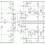
About a push-pull vas (the image are a part of a power amp), in the circuit image I include, Q5 and Q6 are the push-pull vas, Q7 and Q8 are the bias.
But what are the fonction of Q11, Q12, etc... ?
And where do I put a phase lead in that vas of a amp circuit ?
Thank you
Bye
Gaetan
About a push-pull vas (the image are a part of a power amp), in the circuit image I include, Q5 and Q6 are the push-pull vas, Q7 and Q8 are the bias.
But what are the fonction of Q11, Q12, etc... ?
And where do I put a phase lead in that vas of a amp circuit ?
Thank you
Bye
Gaetan
Attachments
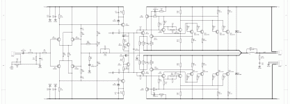
That looks kinda like a Bryston output, PNP+NPN OPs. But Q11 and Q12 are CFP (pre)drivers with gain. You have cut off the IPS and some of the OP so we can only guess the details. If this is working, don't mess with it.
The output is an expanded CFP with a voltage gain of (1K+2K)/1K=3x so the "VAS" stage will provide the global feedback ratio (7150+536)/536 less the output 3x gain, ie 14.34/3=4.78x
The question is, did the designer succeed in getting this design to work reliably. A simple two stage CFP is a stability issue, so a 4-stage output seems to be a recipe for failure. There may be a very good reason that your friend gave you this amp for free. Bits of lead and lag distributed in the feedback loop is contrary to the basic concept of a dominant pole as a means to stability, so the success of this design is doubtful.
The question is, did the designer succeed in getting this design to work reliably. A simple two stage CFP is a stability issue, so a 4-stage output seems to be a recipe for failure. There may be a very good reason that your friend gave you this amp for free. Bits of lead and lag distributed in the feedback loop is contrary to the basic concept of a dominant pole as a means to stability, so the success of this design is doubtful.

