Thanks a lot, this is very helpful. I will take a detailed tour along your suggested references, try to quantify the actual gain mismatch and, depending on that, see what opportunities are out there.
Icon of nail exactly hit on head...One of the BAF videos details the impact of gain mismatch between n & p devices on harmonic distortion. Might be 2016 - a discussion on followers but I think there is another presentation somewhere with scope traces. But it is most recently detailed in the ACA Mini article by Nelson
In the ACA Mini reducing the value of the source resistor on the p channel part increases the gain of that device and provides a better balance between top and bottom - reducing the 2nd harmonic distortion.... Presumably increasing the gain further would generate increasing amounts of +ve phase 2nd harmonic. I guess the suggestion is to look at the relative transconductance of devices and play with the source resistor values within limits (or using the parallel capacitor trick to maintain some DC bias current stability), to get what you want to see / hear - I think a 2 channel scope would be helpful.
I'm building an AB100, using Nelson's boards (and his Gerber files, produced by the firm he recommended) and a diyAudio power supply board (slightly modified by replacing the 3-watt CRC filter resistors with jumper wires). The transformer is an Avel Lindberg (model Y236852 Dual 115v primaries; dual 35v secondaries; 625VA). The PS has 8 x 15,000 uF caps, rated 63vdc. Unloaded, my PS produces about 51 vdc.
I used the diyAudio PS board because I wanted to use 63vdc caps and I couldn't find 4 identical 10,000 uF caps that would physically fit the AB100 board spaces for C3 and C4, and also because I've previously used this PS board on 3 Pass amps and really like it (and it has 6L6's guide support!).
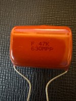
I didn't want to leave those C3/C4 board spaces vacant (okay, I'm a little OCD), so I'm planning to use a "small" electrolytic (6,800 microF) for C3, and a .47 uF, 630v polypropylene film cap for C4. In his article on building a Mosfet HK Citation 12, Nelson said: "...in Fig. 13 are the .47uF/100V capacitors which I placed in parallel with the power supply capacitors to achieve lower dissipation factor at the highest frequencies. These are optional and the amplifier will run quite well without them." Of course, his HK mod has a bypass capacitor across each such electrolytic cap, and I also have 8 x 15K uF caps on the PS board which are not individually so bypassed. Other than filling an empty space on the AB100 board, will my polypropylene caps have any usefulness at all? Any drawback? I also have a bunch of axial polyprop. 2uF units that would fit, standing up in the C4 spaceif that would somehow be better.

The amp will reside in a custom chassis I've built using two fairly good-sized heatsinks, each fitted with brackets designed to hold and surround the circuit boards and to mount the output transistors. The latter are the same TO-3 units Osscar used in his fantastic 'peasants-with-pitchforks'- themed amp. I will attached some pictures in a subsequent post, to satisfy Zen Mod's yen for photographs (because, as he says: "no porn, no glory").
I used the diyAudio PS board because I wanted to use 63vdc caps and I couldn't find 4 identical 10,000 uF caps that would physically fit the AB100 board spaces for C3 and C4, and also because I've previously used this PS board on 3 Pass amps and really like it (and it has 6L6's guide support!).
I didn't want to leave those C3/C4 board spaces vacant (okay, I'm a little OCD), so I'm planning to use a "small" electrolytic (6,800 microF) for C3, and a .47 uF, 630v polypropylene film cap for C4. In his article on building a Mosfet HK Citation 12, Nelson said: "...in Fig. 13 are the .47uF/100V capacitors which I placed in parallel with the power supply capacitors to achieve lower dissipation factor at the highest frequencies. These are optional and the amplifier will run quite well without them." Of course, his HK mod has a bypass capacitor across each such electrolytic cap, and I also have 8 x 15K uF caps on the PS board which are not individually so bypassed. Other than filling an empty space on the AB100 board, will my polypropylene caps have any usefulness at all? Any drawback? I also have a bunch of axial polyprop. 2uF units that would fit, standing up in the C4 spaceif that would somehow be better.


The amp will reside in a custom chassis I've built using two fairly good-sized heatsinks, each fitted with brackets designed to hold and surround the circuit boards and to mount the output transistors. The latter are the same TO-3 units Osscar used in his fantastic 'peasants-with-pitchforks'- themed amp. I will attached some pictures in a subsequent post, to satisfy Zen Mod's yen for photographs (because, as he says: "no porn, no glory").
Power supply board,

 power wiring, and transformer mounted on amp bottom plate, with back panel folded down to permit testing and assembly
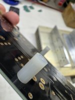
Figuring out how to mount the AB100 circuit board was the first step. Mark Johnson advised someone in this thread that one could use a nylon screw and a nylon spacer to avoid short circuits, and just drill into some bare spaces on the board. I took a similar approach, but decided to drill through the power traces themselves (gulp!), making a small hole for a #6-32 nylon screw in 4 places. I hope this doesn't create any "hot" spots around these holes due to reduction of trace surface area, but there are power traces on both sides of the board, and the 4 holes still leave what seems to me plenty of trace copper around them. We shall see.
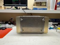
These nylon screws and spacers hold the board in place between two output transistor brackets made from .25 inch thick aluminum brackets (2 inch by 2 inch, no inner radius). To afford some strength, I used very short SS screws and star washers at the bottom of the spacers to attach them to the brackets, but there is no possibility of any connection between these metal pieces and the circuit board. The brackets are to be screwed directly onto the big heatsinks. I drilled and tapped the heatsinks to permit this in a later step.
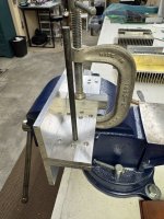
I drilled the brackets for a TO-3 transistor pattern, starting with a small commercial bracket I bought years ago, using it as a template. BTW, It works well to use a "transfer punch" (one of your best metal working tools ever; a whole set available from Harbor Freight tools for a pittance) to mark for drilling holes. I moved the template around to locate holes for 4 output devices on one bracket, and used that first bracket as a template to locate hole markings on the other three brackets. I was pretty careful in this process because I was initially planning to use TO-3 transistor sockets, which requires some accuracy and consistency so they all "snap" into place. But subsequently, Nelson's critical comments in the Mosfet Citation 12 modification article converted me into a socket skeptic and fan of soldered connections. Sigh!
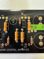


Here is an very early fit-together of heat sinks and panels. The front panel is rough and unfinished at this point, and most importantly has yet to be drilled for the requisite blue LED! Taking a hint from others in these pages, this time around I plan to have the thing splayed open, heatsink/circuit board modules connected to power supply/base plate/back panel by test leads, etc. for the initial power up with variac. If it works, I'll lace it up, and make it tidy. If not, it will be more accessible for the post-mortem. After a brief period of mourning, of course.

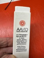
I'm using On Semi MJ11015 (PNP) and MJ11016 (NPN) TO-3 Darlington power transistors, with silicone-impregnated electrical isolation wafers. Without a doubt, Nelson's board design was built on the assumption that those eight plastic transistors in his design would be more than enough support, otherwise he would have provided mounting holes. But I wanted to use the old fashion metal case TO-3 transistors, largely for nostalgic reasons. (The Leach Amps that I built in 1978 (2 channel), and in 1990 (1 channel), and in 2009 (another 1 channel) all used Motorola TO-3 devices, and I like 'em.) Plus, I'm better at metal work than circuit analysis (in fact, I don't know much at all about circuit analysis), so accommodating the physical profile of those old style Qs was more fun than work. BTW, to aid heat transfer from the transistor mounting brackets to the heat sinks, I plan to use this stuff by AAVID, rather than the silicone grease goop. The only drawback is cost. When I bought this stick about 20 years ago the price was about $17, and I've seen it listed now for something like $64!! Anyway, I'm supposing that heat transfer will not be quite as critical for this AB design, compared to Class A.


OK great. I was asking bc I have a bunch of TO3s(metal) here. Would like to try and use some. All from same lot code. You still using 8 per ch?
I don't see the point in using so many TO3 Darlington's = their power is almost 2 times higher than the TIP series...
I am no expert. but looking at the derating, the MJ11015 can handle 7 amps at 30 degrees C. Better than a lot but not that great. Maybe I'm reading the graph wrong.
Reading your signature line looks like you have the HB and the Wolverine? Do you have a preference? I have the HB and think it's an excellent amp. Does the Wolverine sound better?
I built the Badger first and used MT-200 Sanken's. I think it sounds awesome. I am currently using it from 20-200Hz in my main system. The two Wolverines were built later and are currently being used in main system from 200-20kHz. I honestly cannot hear a difference between them. They are both very powerful and produce dynamics extremely well. The Wolverine may measure better, but not sure you can hear a difference.
Hmmm...It didn't occur to me to use less than 8 transistors per channel. I just took Nelson's board layout and went with 8. I guess I could have saved a bit of money by using fewer of them, but I probably would have just squandered the savings on chocolate chip cookies or something equally short-lived. With 8 however, I can look inside the amp and sing:
I've got a lovely line of TO-3s,
There they are sitting in a row.
There stands me wife,
The idol of me life,
Saying "Off your bum"
You got two lawns to mow!
Oh...sorry! In all seriousness, maybe I should use 4 per channel. I bought 5 boards from the company that made them using Nelson's Gerber files. I could build another amp and use them in that. First I gotta make sure this one works, however.
no problem - you can safely use 4 pairs , I also like the look of the TO3. You will be able to use it with a low resistance load.
- Home
- Amplifiers
- Pass Labs
- AB100 Class AB Power Amplifier