
I plan to try the AB100 at lower, +/-30V rail voltages and increase the output bias current as suggested before by multiple members, including NP. Do I really need the 4 output pairs, then? From a SoA point of view even 1 TIP142/147 pair would be safe at 4 Ohm load, whereas 2 pairs seem to be an overkill already. How many pairs would you use at +/-30V rails and why? If it is less than 4 pairs in the end, do I need to adjust something in the front-end?
Thank you,
Miklos
Thank you,
Miklos
Yes, you can reduce the voltage without any problems. usually no changes are necessary. and you can use fewer pairs of transistors at the output. One of my ab100 works without problems on +- 38 V and one pair of MJ11015/ MJ11016 darlingtons.
Thank you, osscar, for confirming. I would be also interested to learn if there are "audible" arguments for more/less output pairs when technically they are all fail safe. I read here and there that "more pairs are better because of lower output impedance and THD" while others say that "single pair is the best due to lacking degeneration issues" etc. Not being experienced enough myself, I am somewhat confused how to find my way across such apparently contradicting statements. What would be your educated guess?
That phrase that says quickly, only thing that happens quickly is trouble, so have to take time to get it right.😉
🙂
🙂
Attachments
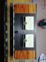
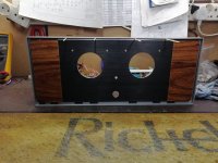
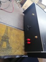
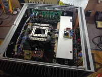
Will hopefully be completed this week. Bought a hole saw for 16mm hole and it cut a 17mm hole on the face plate for the ON/ OFF switch, the we make a plan...
Attachments
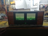
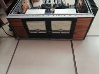
Thanks, need a small black vinyl strip to hide the leds on the bottom of the meters, should do the job, no blue lights !!😉
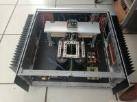
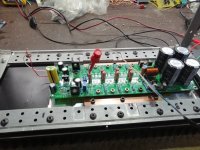
Is the bias with .5R resistors still 20mA per transistor? Pretty sure I had two outputs go up in smoke and then accidentally swapped the NPN and PNP outputs which led me on a wild goose chase. I did figure out you can check the front end by removing the outputs without doing anything special. I then tried just one NPN and one PNP and it worked perfect. I now have all the outputs installed and it is working perfect, just wondering on the bias.
Would anyone in the UK be interested in swapping a pair of AB100 PCB’s for a pair of Aleph J or XA252 PCBs? I need a summer amp.
Only calibration of the meters left to do, thanks goodness this nipper is finished.Tooo many things happening in between to steal one's time.
😉
😉
Attachments
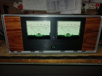
I recommend that you adjust the meter-driving circuitry such that: even when the amp outputs are clipping, the meter needles don't swing all the way to the right and hit the pegs. If something goes wrong and your amp does experience prolonged clipping, you don't want that to damage both the amplifying circuits and the meters.
BTW a sinewave whose amplitude is 80.0 volts peak-to-trough, delivers 100 watts RMS into an 8 ohm load. That's one datapoint for an iterative calibration procedure.
BTW a sinewave whose amplitude is 80.0 volts peak-to-trough, delivers 100 watts RMS into an 8 ohm load. That's one datapoint for an iterative calibration procedure.
I think it's 10mV over 0.5ohm resistor Ray , which translates to 20mA quiescent currentIs the bias with .5R resistors still 20mA per transistor? Pretty sure I had two outputs go up in smoke and then accidentally swapped the NPN and PNP outputs which led me on a wild goose chase. I did figure out you can check the front end by removing the outputs without doing anything special. I then tried just one NPN and one PNP and it worked perfect. I now have all the outputs installed and it is working perfect, just wondering on the bias.
The Aleph 5 is really nice in warming up the room during winter, but it is rather unpleasant during summer.
Is it possible to modify it to class AB push pull by adding P channel MOSFET?
Is it possible to modify it to class AB push pull by adding P channel MOSFET?
can you just adjust the Bias with the A5 ? , with my F7 bias at 800ma for the summer and 1.4A for the winter 😎The Aleph 5 is really nice in warming up the room during winter, but it is rather unpleasant during summer.
Is it possible to modify it to class AB push pull by adding P channel MOSFET?
- Home
- Amplifiers
- Pass Labs
- AB100 Class AB Power Amplifier