Has anybody looked at this and updated it to more modern (available) parts?
It's still an awfully interesting design... we shouldn't let it wither away.
I'm going to bump this thread and hope we get some more interest in it. I have found myself playing with an old Soundtream D-200 amp that I picked up with a dead power supply and it got me thinking about this thread again. I still have a great big old Threshold chassis with massive heat sinks just waiting for the right project.

I think if this is pursued (and I would love to see that) it should be made on the UMS and all on one PCB per channel.
The New PSU board will be great for it, and it would be fairly easy to get it all together and going.
I still think the most logical place to start is determining what would be the logical (and easy to get) modern transistor substitutions. I know absolutely nothing about that, is there anybody who has knowledge in that area willing to take a look and make a list?
I think if this is pursued (and I would love to see that) it should be made on the UMS and all on one PCB per channel.
The New PSU board will be great for it, and it would be fairly easy to get it all together and going.
I still think the most logical place to start is determining what would be the logical (and easy to get) modern transistor substitutions. I know absolutely nothing about that, is there anybody who has knowledge in that area willing to take a look and make a list?
I remember looking at what I had in my parts bin when nelson first published this.
And I came across a few denon recevers 8yro or so. And they had darlingtons that would fit the bill.
I can send you guys the sheets on those. You can decide if they are good or not. All I could decide if they wouldn't let the smoke out that's as far as I got.
yeap .... but then you need to place the question of how far you may go with transistors with Cob of 400-600 pf , ft of about 3Mhz and hfe of 75...
Pretty rugged and robust devices probably ideal for a low pitch inverter ....
kind regards
Sakis
Pretty rugged and robust devices probably ideal for a low pitch inverter ....
kind regards
Sakis
The PMD16K100 and 17K100 from the original A40 are still available if looking for TO-3 style xsistors.
Craig
Craig
If the devices are TO-220, -247 or -3P, they would be able to be used on the Universal Mounting Spec chassis from the store.
I should think they would do the job, and fewer of them.. Of course you
don't at all have to use darlingtons. It's trivial to put together a driver stage.
😎
Mr. Pass. Will you allow me as the starter of this thread [and the other contributors] to propose a balanced design for it in future posts?I should think they would do the job, and fewer of them.. Of course you
don't at all have to use darlingtons. It's trivial to put together a driver stage.
😎
Thanks Mr. Pass. The Interest by DIYers in AB100 is growing. My contribution will be positive.I am not the boss, you may propose anything you like.
😎
Best regards
Any objections by DIYers if I showed a proposed balanced design for AB100. I can start a fresh thread!Thanks Mr. Pass. The Interest by DIYers in AB100 is growing. My contribution will be positive.
Best regards
Any objections by DIYers if I showed a proposed balanced design for AB100.
noone else are posting anything right now, so ....
I can start a fresh thread!
plenty of time for that later, if needed 😉
hey, btw, your suggestion, it wouldn't happen to use MJL21193/94 ....😀
Thanks tinitus. The proposed schematic of a balanced diyAB100 does not include any specific recommendation for devices.noone else are posting anything right now, so ....
plenty of time for that later, if needed 😉
hey, btw, your suggestion, it wouldn't happen to use MJL21193/94 ....😀
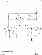
Conjoined Twin diyAB100s
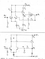
The attached image [SimpleAB100.jpg] shows two simplified schematics of diyAB100. The schematic at the bottom of the view is a further simplification of the top one. I am able to carry on the conversation without showing the output stage to enhance clarity; because the phase of the half shaded sine wave signals is identical in both schematics.
The second attachment "ConjoineddiyAB100s.jpg" is a proposed schematic for the balanced amp. The Right and Left channels are the highly simplified bottom schematics in the previous image. The general benefits of balanced designs are well known. My primary focus is to show the additional performance benefit from "conjoining" the two amps beyond the established ones of balancing. The operation of this balanced amp is very much similar in concept and application to that described in the patent US 5,376,899; inventor Nelson S. Pass.
The Left and Right amps are joined at the emitter ports of Q6 and Q6'. Jumper J can be a wire, a high quality coupling capacitor or a resistor.
The post to follow will explain the operation of the balanced amp in more detail.
Best regards.
Attachments
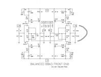
The schematic of conjoined twin diy AB100 above is different from that of balanced BA3. Please see the thread "Bridge a pair F5s" for more detail. I 'll use BBA3 FE as a working example.balanced BA-3 ?
Last edited:
- Home
- Amplifiers
- Pass Labs
- AB100 Class AB Power Amplifier