Since there is nice artwork on the table already, I can devote my time
to something else.
🙂
Can you disclose Wayne's parts suggestions and the grade/rank of the parts? I think that the KSC/KSA parts in the posted artwork are not obtainable in the E-grade.
The KSA/KSC parts appear to not be available in matched grades. One is only available in D grade and the other is only in E grade. Weird.
The BD139 and BD140 appear to be intended for audio amplifier VAS usage. These are what are being used in the PeeCeeBee thread for VAS in the Solid State forum.
The BD139 and BD140 appear to be intended for audio amplifier VAS usage. These are what are being used in the PeeCeeBee thread for VAS in the Solid State forum.
beautiful PCB,. but what psu and transformer do you suggest to use ?? x transistors, you need to Matching ???yea, but Mr. Pass also use two really big electrolytics in B1 buffer 😀
Attached!
BTW, this is my last "mod" attemp (rounded tracks).
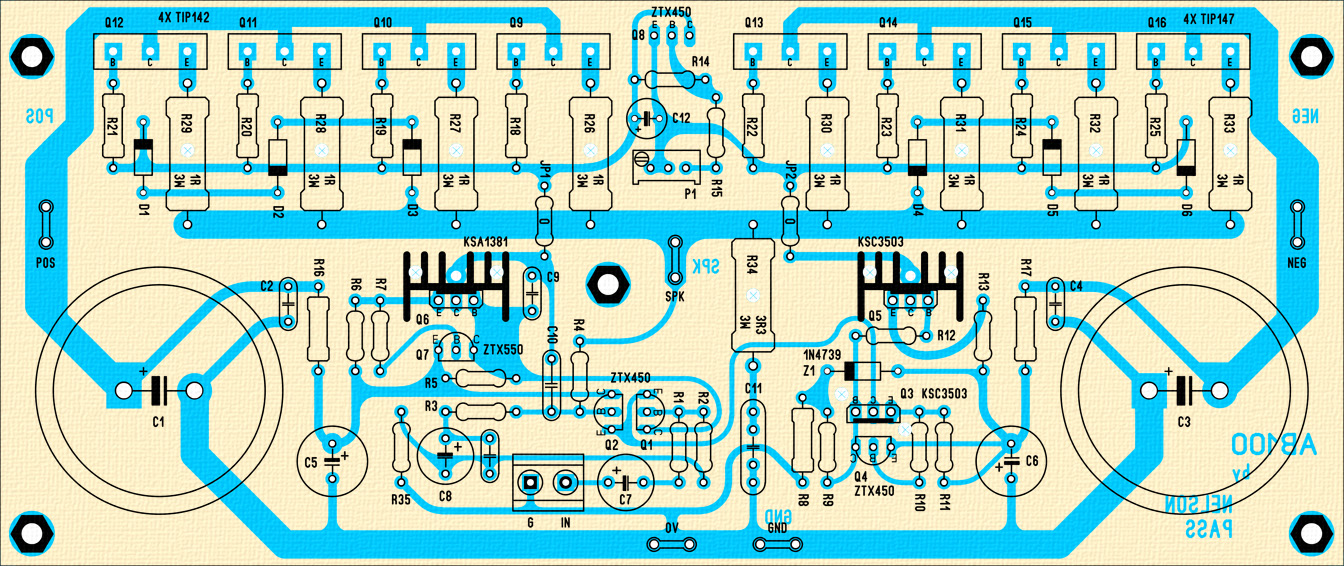
dim' : 190*80mm
Feel free to modify it yourself.
ZIP :
preview.jpg
*.Lay6 files
Gerber & Drill
I want to go to a cave, ascetic and growing beards.
doesn't sleep yet since yesterday.
beautiful PCB,. but what psu and transformer do you suggest to use ?? x transistors, you need to Matching ???
If we are lucky to have the final PCB on the store, I suggest we gently invite 6L6 to a nice build guide...

Maybe like this? :
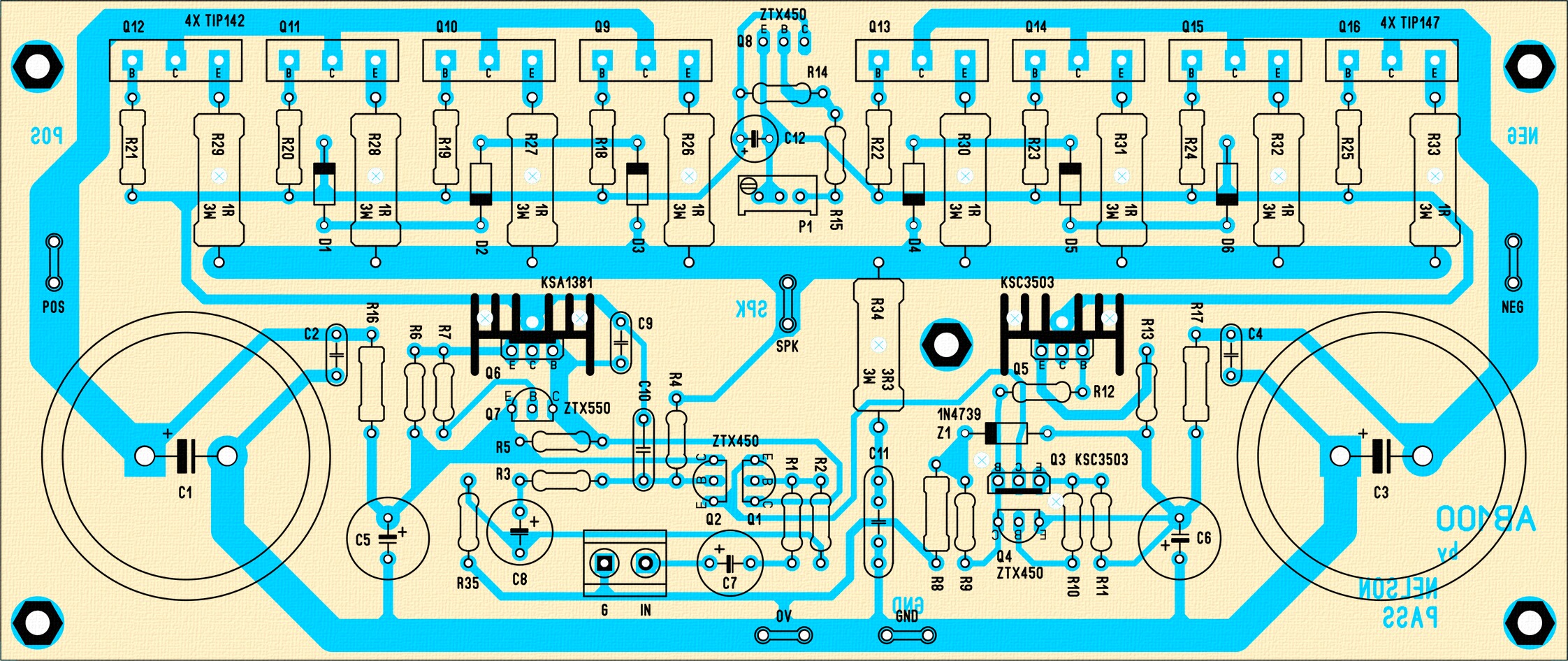
Q8 should be spun around so that the flat side can be clamped to the heatsink. The pads and holes for the power transistors Q9-Q16 should be enlarged to ease assembly and later repair. The +/- rails can be moved from the edge of the board to under the base and emitter resistors. Just move the protection diodes.
I think BD140 wouldn't be a good choice as a VAS transistor, too slow, compared to 2SA1110.The BD139 and BD140 appear to be intended for audio amplifier VAS usage. These are what are being used in the PeeCeeBee thread for VAS in the Solid State forum.
What diameter do you suggest?The pads and holes for the power transistors Q9-Q16 should be enlarged to ease assembly and later repair.
I think BD140 wouldn't be a good choice as a VAS transistor, too slow, compared to 2SA1110.
If I read correctly what Nelson wrote, the choice of components was what was available to him in his stash from Adcom. That VAS transistor is obsolete.
The real question should be "What VAS transistor can meet -3dB at 100kHz ?" A 200 MHz VAS transistor is a bit overkill unless you have an already paid-for stash.
I have a small stash of BD139/BD140 as well as KSA/KSC parts at grade E. I could donate a couple of pairs of each to the cause of enlightenment once we have a final board layout.
If we are lucky to have the final PCB on the store, I suggest we gently invite 6L6 to a nice build guide...
For it to be in the store, it has to fit the Universal Mounting Specification...
😀 😀 😀
https://cdn.shopify.com/s/files/1/1006/5046/files/universal-mounting-specification-v2.1.pdf
For it to be in the store, it has to fit the Universal Mounting Specification...
😀 😀 😀
https://cdn.shopify.com/s/files/1/1006/5046/files/universal-mounting-specification-v2.1.pdf
That shouldn't be such a great trouble, am I wrong?
I have been receiving emails asking for the Great and Powerful Pass
version. Since it is largely done and conforms to the universal mounting
spec for 10 output devices, I guess I'll finish it after all.
If you can't wait, then go ahead with the other. 🙂
version. Since it is largely done and conforms to the universal mounting
spec for 10 output devices, I guess I'll finish it after all.
If you can't wait, then go ahead with the other. 🙂
We can and will wait. Thanks Mr. Pass. Not necessary to say a big thank you to the other guys working on their own great PCB. But Papa is Papa.
What diameter do you suggest?
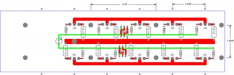
{all dimensions in inches}
When I prototype stuff like this I use a Keystone #34 eyelet that is about .150 diameter and requires a .093 hole. Inside hole is about .068 after I install the eyelet with my non standard tool. For a double sided PCB I'd use a square pad about .190 or .200 and a .065 +/- .003 hole. It might be nice to enlarge the pad vertically and drill a via about .100 from the component hole.
hi, but x the psu are 45v DC?🙂Amp ha been completed and it sings like crazy 😀
Everything worked even without test boards. No hum, dc offset 2mV and 10mV per channel.
Bias 40mA per transistor - runs cool.
no turn on/off thumps.
PSU - +- 45V 30 000Uf in each rail.
indicator diode foe each rail.
Transistors - ztx450,550,MJ340/350, mj11016/15.
0,5 ohm emitter resistors and base stopper divided-100R on PCB and 100 on transistor base pin.
I will measure later with scope and sound-card - now I am a little tired after amp hobby work 🙄
Hi, i do not understood your question correctly, but if you asking about psu voltages:
Transformer 2*32V ac and approx +- 45V DC
Transformer 2*32V ac and approx +- 45V DC
hi, I meant this thanksHi, i do not understood your question correctly, but if you asking about psu voltages:
Transformer 2*32V ac and approx +- 45V DC
The KSA/KSC parts appear to not be available in matched grades. One is only available in D grade and the other is only in E grade. Weird.
have a look at the KSA1220A/KSC2690A 160v 175Mhz, Cob is a bit higher... 26pF v(19Pf) but both available in "Y" 160-320 classification.
The KSA/KSC parts appear to not be available in matched grades. One is only available in D grade and the other is only in E grade. Weird.
have a look at the KSA1220A/KSC2690A 160v 175Mhz, Cob is a bit higher... 26pF v(19Pf) but both available in "Y" 160-320 classification.
That is excellent. Than you for the info on matched VAS transistors. We will have to await Nelson's official schematic for the actual devices.
From Mr Pass
Hope he doesn't mind I posted this here.
Somewhere, can't remember where, I promised some work on the AB100
pc board by way of update, and later decided that I would try melding it
with a modular output stage that would support an open design and
make it available through the store.
Toward that end I started fitting it to the UMS spec of DIYaudio, and here
it is currently, with up to 10 output devices and room for the 20 pin
socket holding a front end.
At this point I am just entertaining the notion of a layout that looks like
this with something like these dimensions.
These pinouts support complementary followers for TO-3P type packages
in both Bipolar and Mosfet. Digikey shows 95 such Bipolars.
Comments welcome.
Attachments
- Home
- Amplifiers
- Pass Labs
- AB100 Class AB Power Amplifier