xplod1236 said:I have acquired a schematic for this amplifier, but I don't want to post it here due to copyright. I was wondering if anyone would be willing to shoot me an email, take a look at the schematic, and suggest which other components (besides the obviously fried ones) to check/replace. I don't want to put in ~$80 worth of transistors (what I found so far) only to have them fry again. My email is [my username] @gmail.com. Thanks in advance.
It's not like anyone from AB Systems is going to chase you. I knew
Bob Byrd personally from ESS, and also George Anderson (still
alive but retired), in fact George drew up the chassis prints for the
Threshold 800A.
One of the other ex-principals is a neighbor of mine, and a very
nice guy (Jeff Kuells).
If you haven't fixed it already and want a cheap opinion, you know
where to email me.
😎
AB Systems has been great to me.
I called and asked for schematics for the 900 and 1100 and told them I just wanted to see what they were doing.
They provided them free of charge.
Of course I own several AB models now, it was a good investment for them.
I called and asked for schematics for the 900 and 1100 and told them I just wanted to see what they were doing.
They provided them free of charge.
Of course I own several AB models now, it was a good investment for them.
eva: UF1004 could be used, 1A 400V ~50nS (depends on maker).
Yeah, that impedance wasn't very flat 😀 IIRC the power dissipated in output transistors decreased rather than increased when the load was made more reactive. Especially at full power out. This was with the middle rail at half high rail. I understand the middle rail should be higher than that for best efficency with continous sinewaves, but this doesn't hold for music with its high peak-to-average ratio does it? It seems half voltage is commonly chosen.
Yeah, that impedance wasn't very flat 😀 IIRC the power dissipated in output transistors decreased rather than increased when the load was made more reactive. Especially at full power out. This was with the middle rail at half high rail. I understand the middle rail should be higher than that for best efficency with continous sinewaves, but this doesn't hold for music with its high peak-to-average ratio does it? It seems half voltage is commonly chosen.
I have ordered the components last night. As for the BDX54F, I have emailed AB, and one is on the way from them. 🙂 Overall, I have spent about $100 on the parts; I should be receiving them by the end of the week (hopefully).
I would like to thank everybody that has taken the time to contribute to this repair. I will post updates as stuff gets done, or if I have any more questions.
I would like to thank everybody that has taken the time to contribute to this repair. I will post updates as stuff gets done, or if I have any more questions.
Be careful 🙂
Yes, audio has a high peak to average ratio and equal rails tend to produce the highest efficiency. Once I wrote a program to analyse wav files and calculate class G/H amplifier efficiency (resistive load) with different rail configurations. Then I became more interested in class D as it allows for efficiencies well over 90% with far less complexity (like 800W@4R with two TO-220 MOSFET as the only output stage).
Yes, audio has a high peak to average ratio and equal rails tend to produce the highest efficiency. Once I wrote a program to analyse wav files and calculate class G/H amplifier efficiency (resistive load) with different rail configurations. Then I became more interested in class D as it allows for efficiencies well over 90% with far less complexity (like 800W@4R with two TO-220 MOSFET as the only output stage).
I had good luck rebuilding my 9620. Check your fans. They're 48V and if they fail will cause the amp to go into meltdown. A guy at AB recommended changing them to 120vac fans.
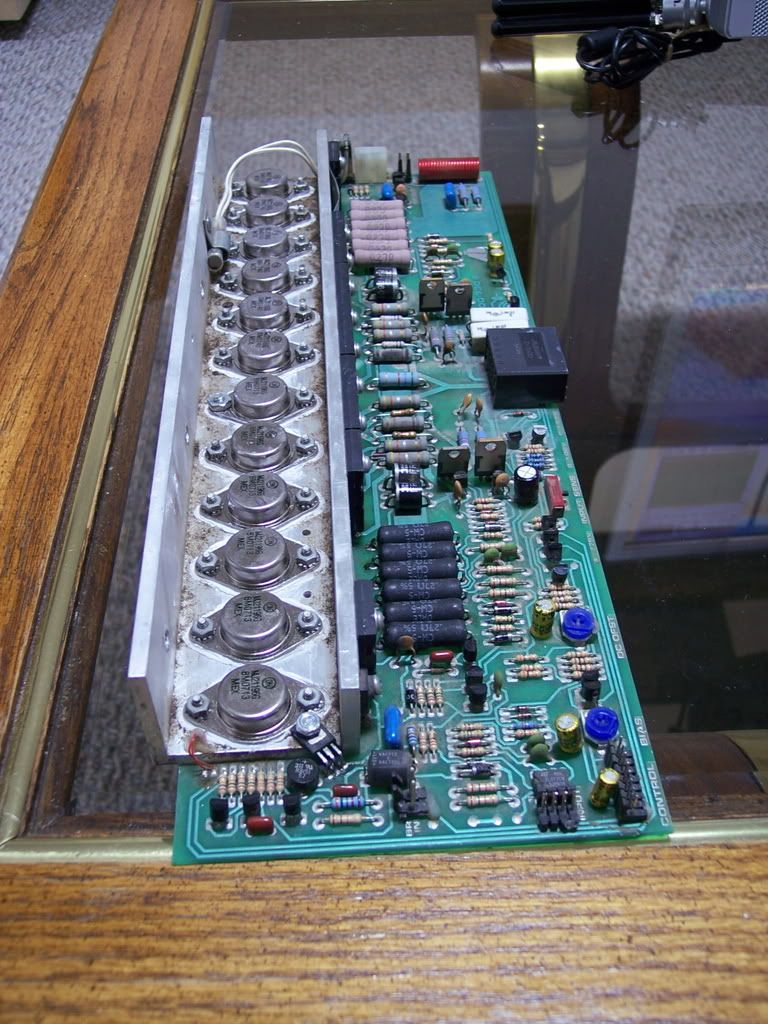
Both channels were blown on my amp. The top channel had a hole burned thru it that I patched with epoxy, redrilled and installed flameproof resistors, rewired with point to point wiring. Be sure to clean out ALL the carbon. I used JB weld for the patch material. Believe it or not, it is non conductive!
Check your bias pots and make sure they're not open- an amp killer. Also check your bridge rectifiers in the PS. Replace all burned resistors with flameproof types. Overall it was an easy repair but time consuming. Probably put $50 in parts from Digikey in it.
LAJ said:Check your bias pots and make sure they're not open- an amp killer. [/B]
I put a zener across my bias ccts so they cant go too high a voltage.
I've seen that zener mod before. Its a recommended mod for Yorkville AP3400 and probably others.
The AB guys are really helpful. Their email is ABservice@abamps.com
They really hate to see their equipment go into the dumpster (which is where I got mine from).
The AB guys are really helpful. Their email is ABservice@abamps.com
They really hate to see their equipment go into the dumpster (which is where I got mine from).
LAJ said:I've seen that zener mod before. Its a recommended mod for Yorkville AP3400 and probably others.
The AB guys are really helpful. Their email is ABservice@abamps.com
They really hate to see their equipment go into the dumpster (which is where I got mine from).
Yes I got fed up having to replace 6 MOSFETs after starting with the bias pot at the wrong end ! Al lall for the sake of a cheap little zener.
Full CCW on the 9620.
Some amps you can get at the bias pot from either side of the board (like Yorkville's AP3400).
In that case, its CW from the BOTTOM side of the board.
Some amps you can get at the bias pot from either side of the board (like Yorkville's AP3400).
In that case, its CW from the BOTTOM side of the board.
And do start it with a series light bulb in case there are something still broken or the bias pot was turned the wrong way.
Most amps should have the bias lowest at CCW but don't depend on it generally as the designer might have made it backwards for some obscure reason.
Most amps should have the bias lowest at CCW but don't depend on it generally as the designer might have made it backwards for some obscure reason.
Or you could just get a variac. I use a Superior 10B powerstat. Its only good for 2.5A but your idle current shouldn't run any more than that. And you'll need an ampmeter as well. I've seen those powerstats on Ebay for as little as $8.
Sometimes when the schematic file gets transferred to the artwork the pots DO get reversed.
Sometimes when the schematic file gets transferred to the artwork the pots DO get reversed.
LAJ said:Or you could just get a variac. I use a Superior 10B powerstat. Its only good for 2.5A but your idle current shouldn't run any more than that. And you'll need an ampmeter as well. I've seen those powerstats on Ebay for as little as $8.
Sometimes when the schematic file gets transferred to the artwork the pots DO get reversed.
Or you could set the bias pot in the middle?
At one extreme or the other could kill the output transistors.
I usually power my new amps up without output transistors connected and then set the bias to minimum.
You can't be sure middle will be ok. It depends on how big they made the adjustment range. Start from minimum.
I have a 3000VA variac but I still find the light bulb trick useful - it will protect somewhat if the bias runs away for example.
I have a 3000VA variac but I still find the light bulb trick useful - it will protect somewhat if the bias runs away for example.
I agree. Most of the bias pots I've screwed around with, I found 10 o'clock to 11 o'clock position to be the proper setting.
Now the 9620 should have some whiteout looking stuff on the bias and DC offset pots to secure them. So that is a good place to start.
Alternatively, you could always look at the schematic and determine what direction is minimum.
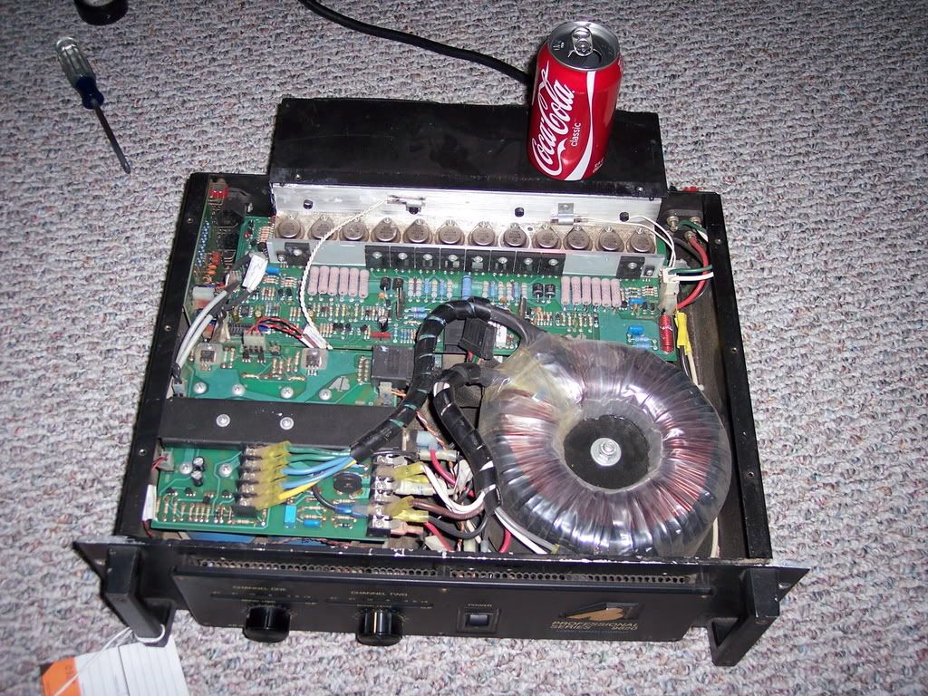
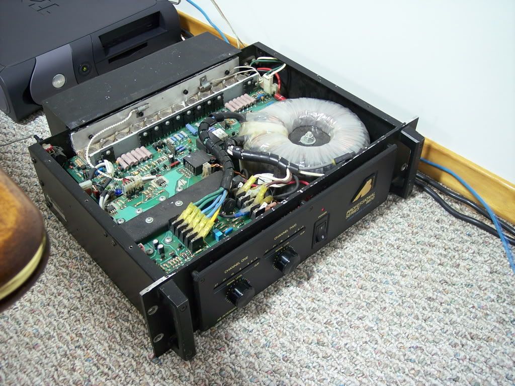
That 9620 is a real man's amp! At 56 pounds, you've got to be a real man just to pick it up!
Now the 9620 should have some whiteout looking stuff on the bias and DC offset pots to secure them. So that is a good place to start.
Alternatively, you could always look at the schematic and determine what direction is minimum.
That 9620 is a real man's amp! At 56 pounds, you've got to be a real man just to pick it up!
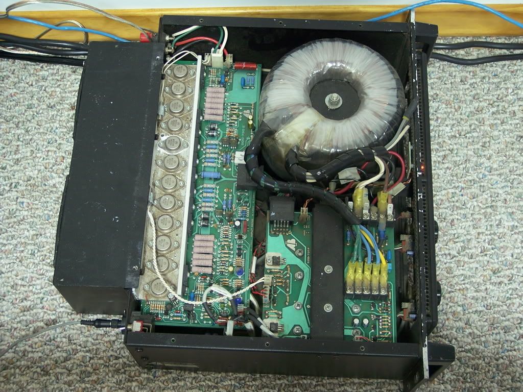
I have one that I took a while ago. The torroid is as tall as the Coke can. I'll take some more pictures later tonight.
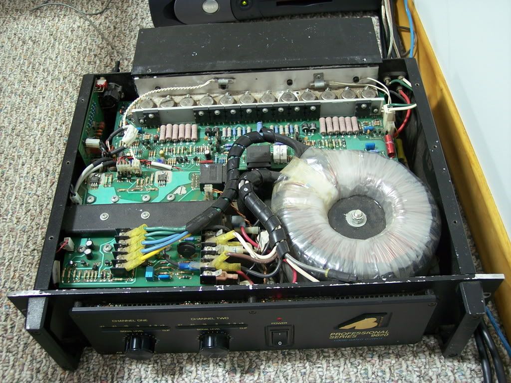
Yes, thats it all right.
This one doesn't have the speaker ground mod.
There is a factory mod that takes the grounds (green wire) for each speaker, cuts them loose from the molex connector (that plugs into each amp board) and connects them to the center of the power supply main caps on the power supply board.
And this one is still using DC fans. The DC fans are the two red and black wires on the left center of the amp.
- Status
- Not open for further replies.
- Home
- Amplifiers
- Solid State
- AB international 9620 amp with blown channel