...
I remember the words of a friend who has serviced an Aaaron No3. Millennium before, that this amp had some problems with current.
I will ask him to explain better, maybe to help us.
Finally, It is not true the above. There in no any current problem to the amp.
He told me that the transistor output are MJ150024/25 probably. These transistors are used to Sovereign amps.
He told me that the pairs of MJ15003/4 are very-very closely to MJ150024/25 with better linearity.
This an old thread, but now I have some more information about this.
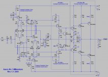
At the following diagram, a revision 1.1 is demonstrated

I found another one revision (?) with some changes from the rev. 1.1

A differential symetrical input stage at the left with BC550c/560c pairs, a VAS stage with BC639/640, a triple CFP Common Emmiter Stage with a local feedback at the output with a BC639/640 pre-driver, a BD243c/244c driver and a BJT output maybe 15003/15004 or 21193/21194 (explained at the end).
At the output a zobel network RC and the global feedback net to the differential inputs.
I found that this topology is very close with the Bryston CFP Stage.
It is very important that the pairs (npn-pnp) of pre-driver, driver and output transistor have same hfe, due the CFP topology.
It is very difficult to repairing it, if someone transistor has gone.
Driver hfe must be 25-50, output transistors under 100, VAS 100 around and the input differentials much paired on Vbe.
The quiescent current must be 27-36mA, 6-8mV drops on 0R22 resistors.
Output transistors about
At the previous messages had been reported from the member Andrew-T, that the MJ15003/15004 bjt are the Aaron's No3 Millennium tranzistor.
I measured 3 original No3. Millennium bjt and the hfe was 60 (same for the pnp-npn) for the one channel and 71 for the other.
The most possible Aaron bjt's that had been reported are 15003/4, 150024/25 and 21193/94.
The 15003/4 have a hfe until to 150, the 150024/25 until to 60 and the 21193/94 until to 75.
I believe that, a low hfe 15003/4 had been used or 21193/94 pairs.
At the following diagram, a revision 1.1 is demonstrated
I found another one revision (?) with some changes from the rev. 1.1
A differential symetrical input stage at the left with BC550c/560c pairs, a VAS stage with BC639/640, a triple CFP Common Emmiter Stage with a local feedback at the output with a BC639/640 pre-driver, a BD243c/244c driver and a BJT output maybe 15003/15004 or 21193/21194 (explained at the end).
At the output a zobel network RC and the global feedback net to the differential inputs.
I found that this topology is very close with the Bryston CFP Stage.
It is very important that the pairs (npn-pnp) of pre-driver, driver and output transistor have same hfe, due the CFP topology.
It is very difficult to repairing it, if someone transistor has gone.
Driver hfe must be 25-50, output transistors under 100, VAS 100 around and the input differentials much paired on Vbe.
The quiescent current must be 27-36mA, 6-8mV drops on 0R22 resistors.
Output transistors about
At the previous messages had been reported from the member Andrew-T, that the MJ15003/15004 bjt are the Aaron's No3 Millennium tranzistor.
I measured 3 original No3. Millennium bjt and the hfe was 60 (same for the pnp-npn) for the one channel and 71 for the other.
The most possible Aaron bjt's that had been reported are 15003/4, 150024/25 and 21193/94.
The 15003/4 have a hfe until to 150, the 150024/25 until to 60 and the 21193/94 until to 75.
I believe that, a low hfe 15003/4 had been used or 21193/94 pairs.
Last edited:
There is gain in the output section... for some reason they decide to run LTP + VAS at 24V and then make up the loss with a gain of two in the output.
Output stages with gain are notorious for instability. Looks like they revised the compensation in Rev 1.1, so I guess they knew there were problems!
Output stages with gain are notorious for instability. Looks like they revised the compensation in Rev 1.1, so I guess they knew there were problems!
Yes, there is a zener 24V on 49V rail, for that reason, but the VAS Q7,Q10 (BC639/640) feeds by 18...19V. The Q5, Q8 runs on 21...22V almost.
I can't see any difference at gain between rev.? and rev 1.1 at the output stage!
The adding of pre driver, I think adds a current-gain stage between VAS and drivers.
The output pairs Q15,16 and Q17,18 is identical output like the Complementary Feedback Pair (CFP) output stage in common-emitter (CE) mode, this is described at the "Designing Audio Power Amplifiers - B. Cordell (1st edition, 2011)".
According to Cordell this is operated in the common-emitter (CE) mode rather than as emitter followers. It has a high degree of local feedback that linearizes each half of the output stage [4]. This results in very low output impedance for each half of the output stage and thus, presumably, reduced crossover distortion.
Each of the upper and lower CFP stages acts like a super emitter follower with extremely high transconductance.
Adding an emitter follower as predriver (Triple CFP mode), it adds two Vbe to the required mount of bias spread and does not change any of the stability or transconductance characteristics of the CFP.
R1 @ 22k gives a high noise contribution with this high gain amplifier.
I calculate the noise due to this 22k resistor to be ~0.14mVrms @ the output, (that's in addition to noise created by the amplifier).
The input filter is set by the two RC components to ~300kHz.
Could the resistor R1 be changed to 2k2 and the capacitor C1 to 220pF? (this takes the added noise from the resistor down to ~0.05mVrms).
Would this affect stability in any way?
Going a bit further, would 2k2 and 390pF cause a stability issue?
Last edited:
Andrew, there are two diagrams at the post #42 as you saw.
The first is from rev. 1.1 and the second from another uknown revision.
I don't know which is newer.
At the rev. 1.1 the RC input filter is very high, almost 3.82MHz.
At the rev. XX the RC filter is at the 382KHz.
From what I know, the Bryston amplifiers (2B, 3B, 4B) use the combination of 2K2 + 220pF, maybe I have see wrong the input capacitor value on the rev.1.1 pcb
RC LPF with 2K2+220pF or 2K2+390pF set the input cut-off at 328KHz and 185KHz respectivly.
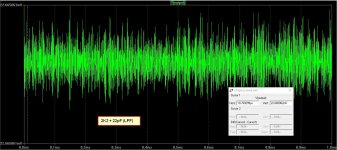
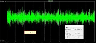
I applied a method to the LTSpice, on rev. 1.1, to measure the noise but I don't know if this is right.
I left the input open and run a AC simulation without any output load.
Here are the results of the output noise.
There is a littler noise in 2K2+220pF vs 2K2+22pF but it is not significant.
The first is from rev. 1.1 and the second from another uknown revision.
I don't know which is newer.
At the rev. 1.1 the RC input filter is very high, almost 3.82MHz.
At the rev. XX the RC filter is at the 382KHz.
From what I know, the Bryston amplifiers (2B, 3B, 4B) use the combination of 2K2 + 220pF, maybe I have see wrong the input capacitor value on the rev.1.1 pcb
RC LPF with 2K2+220pF or 2K2+390pF set the input cut-off at 328KHz and 185KHz respectivly.
I applied a method to the LTSpice, on rev. 1.1, to measure the noise but I don't know if this is right.
I left the input open and run a AC simulation without any output load.
Here are the results of the output noise.
There is a littler noise in 2K2+220pF vs 2K2+22pF but it is not significant.
Attachments
Another information from Jammer hij deed het zo mooi - Pagina 3 - forum.zelfbouwaudio.nl
There is a diagram from rev 1.0, it is has been made in 1999, earlier than 1.1
The input LPF is a combination of 11K + 220pF
There is a diagram from rev 1.0, it is has been made in 1999, earlier than 1.1
The input LPF is a combination of 11K + 220pF
An externally hosted image should be here but it was not working when we last tested it.
the added noise from the 2k2 resistor is the same in both cases.Andrew, there are two diagrams at the post #42 as you saw.
The first is from rev. 1.1 and the second from another uknown revision.
I don't know which is newer.
At the rev. 1.1 the RC input filter is very high, almost 3.82MHz.
At the rev. XX the RC filter is at the 382KHz.
From what I know, the Bryston amplifiers (2B, 3B, 4B) use the combination of 2K2 + 220pF, maybe I have see wrong the input capacitor value on the rev.1.1 pcb
RC LPF with 2K2+220pF or 2K2+390pF set the input cut-off at 328KHz and 185KHz respectivly.
I applied a method to the LTSpice, on rev. 1.1, to measure the noise but I don't know if this is right.
I left the input open and run a AC simulation without any output load.
Here are the results of the output noise.
There is a littler noise in 2K2+220pF vs 2K2+22pF but it is not significant.
The filtering effect is different and rolls off the upper frequencies. that the small reduction in noise you are seeing.
It's the 22k that will be very noisy.
Yes Andrew.
I am afraid that I have an error on diagram bias setting Q11,12 (BD139) on revision 1.1.
At the rev 1.0, I see a combination of BD139/BD140 and If I look in the first page at my post #6 at the attachment photos I see that maybe there is a BD140 at the right.
I will update on this information when I am looking at the pcb again.
There is gain in the output section... for some reason they decide to run LTP + VAS at 24V and then make up the loss with a gain of two in the output.
Output stages with gain are notorious for instability. Looks like they revised the compensation in Rev 1.1, so I guess they knew there were problems!
Yes, there is a zener 24V on 49V rail, for that reason, but the VAS Q7,Q10 (BC639/640) feeds by 18...19V. The Q5, Q8 runs on 21...22V almost.
I can't see any difference at gain between rev.? and rev 1.1 at the output stage!
The adding of pre driver, I think adds a current-gain stage between VAS and drivers...
I think that your thought about 2X gain at the output stage is wrong.
Look the situations on following examples.

The circuit in Figure 6.12 gives gain because two potential dividers R5, R1 and R6, R2 have been inserted in the local feedback path to the driver emitters; as you might expect, equal resistor values top and bottom give a gain of 2.
At the Aaron circuit there is no any divider btw drive and output transistor in the local feedback path.
Last edited:
the arrangement of the resistors is different, but I see a voltage divider, feeding a portion of the output into the emitter of the pre-driver.
Here is an update diagram of Revision 1.1 (2015) that I was uploaded at post 42.
I have changed the input LPF, the right is 2.2K+220pF (not 2.2K+22p) and the parallel capacitor on resistor at the NFB with 100p (not 10p).
Also, I make a carefully observation on bias multiplier section and notes some notes on topology of this amp.
I have changed the input LPF, the right is 2.2K+220pF (not 2.2K+22p) and the parallel capacitor on resistor at the NFB with 100p (not 10p).
Also, I make a carefully observation on bias multiplier section and notes some notes on topology of this amp.
Attachments
I am looking the behavior of this revision on LTSpice.
It seems that the pair MJ15003/15004 works well on low frequencies (e.g 1KHz) but at the THD 20K they have problem with the distortion.
At the other side the pair MJ21193/21194 has much lower distortion at all frequencies (20-20K).
I have enclosed the LTSPice simulations.
It seems that the pair MJ15003/15004 works well on low frequencies (e.g 1KHz) but at the THD 20K they have problem with the distortion.
At the other side the pair MJ21193/21194 has much lower distortion at all frequencies (20-20K).
I have enclosed the LTSPice simulations.
Attachments
Last edited:
Changing the nfb cap from 10p to100p is a bad plan.High value cap can make the amplifier unstable and secondly allows interference from the speaker leads to feed directly into the -IN node.
It was my mistake that the NFB had 10p // 5.1K, it was wrong observation with the mark that I saw.
Before some days, I re-solder the original cap and the measurement was 100p exactly.
In LTSpice there is an oscillation with the 10p parallel to 5.1R and makes to normal with the 47-100p values.
The same wrong was and to the input LPF, it wasn't 2.2K+22p as I had said before but the right is 2.2K+220p.
- Status
- Not open for further replies.
- Home
- Amplifiers
- Solid State
- Aaron Millenium 3, outputs transistors & quiescent current