Aaron No3. Millennium, output transistors & quiescent current
Hi @all,
I have an Aaron Millennium 3, ver1.1 (20/06/2005) with problem on an output transistor - left channel - (unfortunately the signs of transistor has deleted from the factory).
I have find a schematic from Aaron 3 and according to this, the output transistors are pairs of MJ15003/15004. Is that true and happens to all Aaron versions?
If somebody have any other schematics about this final amplifier, I will appreciated!
Also, I would like to set the right quiescent current (procedure and values).
Thanks
Last edited:
My Aaron is fitted with MJ15003/4 outputs.
Aaron literature tells lies about the low impedance capability of their amplifiers.
Aaron literature tells lies about the low impedance capability of their amplifiers.
Do you know, what pcb revision has it? - there is a refference about this, under each pcb.
What you meaning, exactly with "Aaron literature tells lies about the low impedance capability of their amplifiers"?
What you meaning, exactly with "Aaron literature tells lies about the low impedance capability of their amplifiers"?
Aaron says:
Output power continuous sine wave per channel:
100W/8Ω 0.1% THD
160W/4Ω 0.1% THD
Output power pulsed per channel:
350W/2Ω 0.1% THD
410W/1Ω 0.1% THD
At the low impedance loads the "secret" is the term "pulsed"...they don't use the term "sine wave". Factory trick!
I have the equipment to measure all of this, but I haven't the appropriate "dummy load" for this power. Usually, I use "dummy load" until 60W/4-8 Ohm.
Yesterday, I found the problem to the right channel and fixed. I have some measures (thd+N, imd) between left & right channel (left has the new MJ15003/15004G, right has the factory tranzistor).
I will upload to my next message.
Cheers.
Happy New Year to all!
I come back with my Aaron No3. Millennium.
At listening test, everything is OK, but if you place your ear to the right speaker there is a "zzzz" from midrange & tweeter.
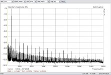
This appears and with thd+N metering, that there is a difference 0.023% vs 0.073%, with the noise threshold at the R channel more higher. I believe that the cause must be some transistor.
THD+N(%) Left Channel

THD+N(%) Right Channel

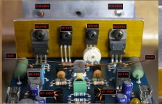
Also, my pcb differs from above schema (first message). I have per pcb 18 tranzistors vs 17 tranzistor that appears at the schema. I have enclosed two photos from my pcb.
I would be happy if someone gave me an extra pcb schema like mine board.
I come back with my Aaron No3. Millennium.
At listening test, everything is OK, but if you place your ear to the right speaker there is a "zzzz" from midrange & tweeter.
This appears and with thd+N metering, that there is a difference 0.023% vs 0.073%, with the noise threshold at the R channel more higher. I believe that the cause must be some transistor.
THD+N(%) Left Channel
THD+N(%) Right Channel
Also, my pcb differs from above schema (first message). I have per pcb 18 tranzistors vs 17 tranzistor that appears at the schema. I have enclosed two photos from my pcb.
I would be happy if someone gave me an extra pcb schema like mine board.
Attachments


My Aaron is fitted with MJ15003/4 outputs...
Is your amp, Aaron 3 or Aaron No3. Millennium?
Aaron No.3 Millennium
http://aaron.hifi.net/intl/no3.html
this is the lies. It's fromHere, you will find the right connection for the best speakers.
With output of
2 x 100 Watt at 8 Ohm
2 x 180 Watt at 4 Ohm
2 x 320 Watt at 2 Ohm
2 x 550 Watt at 1 Ohm
the No.3 Millennium is of course able to drive even impedance-critical speaker systems.
http://aaron.hifi.net/intl/no3.html
Last edited:
most likely it is, that one of the transistors T1-4 has been noisy.Happy New Year to all!
I come back with my Aaron No3. Millennium.
At listening test, everything is OK, but if you place your ear to the right speaker there is a "zzzz" from midrange & tweeter.
This appears and with thd+N metering, that there is a difference 0.023% vs 0.073%, with the noise threshold at the R channel more higher. I believe that the cause must be some transistor.
Check also the zeners Z1+Z2 so as the electrolytics C2+C3 (perhaps you add bypass caps, e. g. WIMA MKS, 1uF - 4,7uF).
What happens with the difference in noise, if you short the input to GND (short therefore C1 resp. R2) ?
About
http://new.audiogon.com/listings/433779
there are various pics.
Last edited:
Aaron No.3 Millenniumthis is the lies. It's from
AARON ® No.3 Millennium * The High End Stereo Power Amplifier from Germany
- I agree with you, AndrewT. There is a "trick" at 2 & 1 Ohm from Aaron (pulse measuring).
Please, it is very important to me. You said that yours Aaron output transistor are pairs MJ15003/15004. Have you Aaron 3 or Aaron No3 Millennium?
most likely it is, that one of the transistors T1-4 has been noisy.
Check also the zeners Z1+Z2 so as the electrolytics C2+C3 (perhaps you add bypass caps, e. g. WIMA MKS, 1uF - 4,7uF).
What happens with the difference in noise, if you short the input to GND (short therefore C1 resp. R2) ?
About
Aaron No.3 Millennium Stereo High End Amplifier | Solid | AudiogoN
there are various pics.
- Thanks for the respond to me "tiefbassuebertr". The problem has resolved. There was a "cold" soldering at the ground of left channel at the rca input. Now everything is OK.
To all members: I am looking for the kind of output transistor of Aaron No3. Millennium and if there is a pcb diagram, it is welcome!
AndrewT, sorry for the confusing! But the English is not my native language!
In post #8 there is your answering about Aaron's No3 Millennium Power Output.
I ask for confirmation, what is your amplifier in the post#2
In post #8 there is your answering about Aaron's No3 Millennium Power Output.
I ask for confirmation, what is your amplifier in the post#2
My Aaron is fitted with MJ15003/4 outputs...
I have just pulled out the No.3 and did a couple of very basic tests.
Powered up and checked the rail voltages +-48.5Vdc with 50V smoothing caps. I have previously commented on this ridiculous "productionising" decision. 32off 2m2F caps don't cost that much extra in changing from 50V to 63V
Outputs offsets L -24mVdc R +4mVdc.
Shorted inputs offsets L -5mVdc R +5mVdc (it is just warming up).
Shorted inputs output noise L & R flickering between 0.0mVac and 0.1mVac
Open circuit inputs output noise L & R still flickering between 0.0mVac and 0.1mVac but spending a higher proportion of time displaying the higher value.
Further testing of that odd output offset of the L channel, fully warmed up.
Rs=0r0 -4.9+-0.3mVdc
Rs=100r -4.9+-0.3mVdc
Rs=1k0 -5.5+-0.2mVdc
Rs=10k -8.6+-0.1mVdc
Rs=100k -18.2+-0.1mVdc
Rs=open circuit -25+-0.1mVdc
I will need to open up and try to find out why the Left channel is playing up.
Last edited:
Yes post2 answered your original question !!!!AndrewT, sorry for the confusing! But the English is not my native language!
In post #8 there is your answering about Aaron's No3 Millennium Power Output.
I ask for confirmation, what is your amplifier in the post#2
Read !!!!!
I have just pulled out the No.3 and did a couple of very basic tests.
Powered up and checked the rail voltages +-48.5Vdc with 50V smoothing caps. I have previously commented on this ridiculous "productionising" decision. 32off 2m2F caps don't cost that much extra in changing from 50V to 63V
...
With my version too, it is happening the same! I am going to change all of these capacitors with others with 63V rating.
- Thanks, "AndrewT".Yes post2 answered your original question !!!!
Read !!!!!
Topology from post #1 seems to be very similar to Carlos Candeias LEF topology
http://www.diyaudio.com/forums/solid-state/168185-how-does-lef-load-effect-free-amplifier-work.html
http://www.diyaudio.com/forums/solid-state/168185-how-does-lef-load-effect-free-amplifier-work.html
I must say that the schema (diagramm) of post #1 is for Aaron No3, not for Aaron No3. Millennium.
The Aaron No3. Millennium has a different topology in first transistors BC550&560 and some others. I try to make a schema about it, but I have not a appropriate experience about this.
If there is someone with appropriate knowledge about this - and he is available to help us - I can give him the up and down sides of original pcb (photos)
I started that reverse engineering project, but gave up halfway through, because it was simply taking up too much of my time.
...
Outputs offsets L -24mVdc R +4mVdc.
Shorted inputs offsets L -5mVdc R +5mVdc (it is just warming up).
Shorted inputs output noise L & R flickering between 0.0mVac and 0.1mVac
Open circuit inputs output noise L & R still flickering between 0.0mVac and 0.1mVac but spending a higher proportion of time displaying the higher value.
Further testing of that odd output offset of the L channel, fully warmed up.
Rs=0r0 -4.9+-0.3mVdc
Rs=100r -4.9+-0.3mVdc
Rs=1k0 -5.5+-0.2mVdc
Rs=10k -8.6+-0.1mVdc
Rs=100k -18.2+-0.1mVdc
Rs=open circuit -25+-0.1mVdc
I will need to open up and try to find out why the Left channel is playing up.
You have a difference in offset between 2 ch. I think, that the critical limit is above from 50mV.
I looked to my amp for the same in 20Hz...20KHz range.
My offset was -1.60 until -1.90 to one channel and 1.94-2.00 to the other.
Do you know if the trimmer 1K, controls the offset?
yes, the two channels are behaving very differently.
That different behaviour has nothing to due with the accuracy of setting the quiescent output offset.
It's the change in output offset of the L channel as Rs is varied than concerns me. That change tells me there is something worng.
Will it stay the same or will it get better and will it get worse.
I cannot answer those questions, until I do a bit more investigation to find out why the output offset of the L changes with Rs.
- Status
- Not open for further replies.
- Home
- Amplifiers
- Solid State
- Aaron Millenium 3, outputs transistors & quiescent current