This is what it takes to build A75.😉
For more pictures check http://www.diyaudio.com/forums/showthread.php?s=&postid=52954#post52954
For more pictures check http://www.diyaudio.com/forums/showthread.php?s=&postid=52954#post52954
Attachments
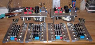
I was under the impression that if I pull the caps together I might eliminate their susceptibility to vibrations and microphonics.😉 I also placed damping material between them.
I have always wondered what are the purpose of the ties around the capacitors. I have seen big can capacitors with metal strap around them. What is the real purpose for doing that?
Metal strap at the bottom of the cap is used to screw the cap to the chassis. It's just a way to mount it.
I meant metal straps that are installed half way up the capacitors .... just like what you did but it's metal strap. I believe I have seen Krell & Threshold amp doing that. Metal strap around the 4 big can capacitors.
Hi,
I recently wondered if it would be a good idea to use capacitor with different size to prevent resonant coupling between them. Sort of what they do in the oil storage tanks. Maybe one could group a different number of caps with the same size to get the same effect.
Also, wouldn't it make sense to reduce the cap size as much as possible to bring the first fundamental resonance out of the audio range? Echoes would have much lower intensity and would be less of a problem.
I heard caps in AC coupled amps resonate and that wasn't pretty. I found it tends to cause loss of focus in the sound.
In the picture, are we looking at 2 discrete audio channels?
Are you using 24 ea TO-3 devices for one channel?
Nice milling.
Aud_Mot
Are you using 24 ea TO-3 devices for one channel?
Nice milling.
Aud_Mot
Two monoblocks, 24 devices per channel, separate active regulation for active stage.
Milling was the only elegant option with TO-3 devices and my sinks. The whole thing can be seen here: http://www.passdiy.com/gallery/a75-p7.htm
Milling was the only elegant option with TO-3 devices and my sinks. The whole thing can be seen here: http://www.passdiy.com/gallery/a75-p7.htm
WOW!
As always I´m impressed by the incredible build quality and the "clean" layout of Your designs!
That`s how professional DIY electronics can look like when made "seriously" and I`m getting a lot of inspiration while looking at this kind of pictures.
Pass Labs could not make it much better I guess😉
As always I´m impressed by the incredible build quality and the "clean" layout of Your designs!
That`s how professional DIY electronics can look like when made "seriously" and I`m getting a lot of inspiration while looking at this kind of pictures.
Pass Labs could not make it much better I guess😉
BTW - Do You use the original Pass regulator for the front-end according the A-75 design article or do You have an own design?Two monoblocks, 24 devices per channel, separate active regulation for active stage.
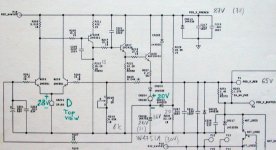
For the front end regulator I used the one from ML23.5. I also have separate windings on the transformer for that purpose (custom made by Plitron).
hm... I like the power supply construction you've got there with the trannie slung under the divider plate, along with some stuff which is presumably the rectifiers and power switch/soft-start circuitry... seems to me you could have the four screws for the standoffs go straight into the amp's feet, and you avoid the big trannie mounting bolt protruding out the bottom of the chassis... Nice idea! I'm going to rip-off this bit of mechanical layout for my Aleph-X monoblocks 😀
So how much did the custom Plitron's set you back, and what VA rating are they?
I might also make a similar bank of small caps. How does the cost and sound of such a capacitor bank compare to the use of larger computer-grade 'lytics?
Cheers,
So how much did the custom Plitron's set you back, and what VA rating are they?
I might also make a similar bank of small caps. How does the cost and sound of such a capacitor bank compare to the use of larger computer-grade 'lytics?
Cheers,
hifiZen said:hm... I like the power supply construction you've got there with the trannie slung under the divider plate, along with some stuff which is presumably the rectifiers and power switch/soft-start circuitry... seems to me you could have the four screws for the standoffs go straight into the amp's feet, and you avoid the big trannie mounting bolt protruding out the bottom of the chassis...
Cheers,
You are right about this. The four screws that go through the amps feet are also used to mount the bottom panel. The divider plate isolates transformer from the rest of the circuit, acts as a mount for transformer and AC filtering, switching and soft start. And since the transformer is not mounted to the bottom panel, the access is very easy in case you have to change fuses.
I used banks of Panasonic HFQ caps since they were pretty good in 1995 (Digi-Key doesn't stock them anymore) and Gary Gallo was raving about them in TAA. I think they cost me around CAD 500. They fit pretty nicely between the bars and are very close to each device so current distribution is better (at least I thought so😉 ) As you look closely you can notice that I didn't use screws to carry the voltage to the devices but rather short pieces of Kimber wire soldered to device cases and the board (it was more pure in my opinion😉 )
I ordered 4 custom transformers from Plitron at the time, and since I persuaded them it's for a prototype and I'll be ordering more in a future I paid around CAD 100 ea. They were 750VA 33-0-33 and 50-0-50 AC.
To tell the truth I never compared the sound of the PS capacitors, I just believed they must have been better.😉
You look MarveLous....
Be nice now. The last time Jocko and I saw the inside of ML product (at a dealer open house) he turned to me and said "What a parts farm!" The ML rep was not amused.... I figure the Wima rep must take the engineers to lunch at least twice a week. To paraphrase Billy Crystal, "It's not how you sound it's how you look."
H.H.
Sorry to say it, but NO.
I just took my Aleph5 to a friend of mine for a listening session (I took A75 before to his place). While he was not really impressed by A75 that much, when he listened to Aleph, he seemed to be in heaven (exageration in a way). He's already collecting parts for Aleph2.
I had to remove half of the parts to convert A75 into Aleph2. I will convert the other A75 into X350 amp when schematics come out.
Hi Peter. I am new to the forum and I am trying to repair a ML 23.5 and was wondering if you had a schematic showing the entire power supply including the transformers etc for the ML 23.5. When I swith the amplifier on I get 240volts (UK) at the power supply PCB but the power on LED does not light nor does the soft start relay click in. Have you any suggestions what the problem may be,
- Status
- Not open for further replies.
- Home
- Amplifiers
- Pass Labs
- A75 revisited