slavko65
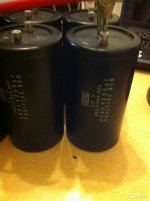
Thank you, do not be offended,I always listen to any opinion. I'm not in a hurry, because the boards are still on the way, and I'm at work. I will take into account all the comments and advice.I have Nover capacitors, 10000mkf 50v, but a 36v transformer, I wanted to buy capacitors with a voltage margin. What are the tips.🙄I will add these banks to them. 😉Attachments
Last edited:
Do you propose to put Nover 10000mkf 50v capacitors on the boards, and add 22000mkf63v outside the boards? The voltage I have is 4X36v, usually capacitors are chosen with multiplication by 1.4, it will turn out 36x1.4 = 50.4v. Correct if I'm wrong. Large capacitors are laid out for a smile.Maybe I'll do something like that.
Attachments
Last edited:
I just had a transformer and capacitors from yamaha dsp-a1000. And I decided to apply them. Therefore, on boards 10,000 should be enough. And yours is beautiful. I was stopped here by the fact that separate transformers, or separate windings, are needed to power the 12-18v protection. Remodel

Indeed, separate secondaries of the transformer for speaker protection is mandatory. One of terminals for 12VAC is connected directly to the ground. Using just one winding creates very loud ground loop. I use a transformer with single primary and two completely separated secondaries.I just had a transformer and capacitors from yamaha dsp-a1000. And I decided to apply them. Therefore, on boards 10,000 should be enough. And yours is beautiful. I was stopped here by the fact that separate transformers, or separate windings, are needed to power the 12-18v protection. Remodel
Over the week end I plan to publish quite few measurements and a comparison CDIL (2SA) vs. ONS (KSA) input stage transistors.
I wish you all a peasant week end and ongoing holidays.
Not so much different. The answer is written on the board: ver 1.0. We have 1.1.Strange, I have completely different boards.
But your idea to place the Zobel on board is fine.
But you need some design margin. In your situation 63V is the right choice.Do you propose to put Nover 10000mkf 50v capacitors on the boards, and add 22000mkf63v outside the boards? The voltage I have is 4X36v, usually capacitors are chosen with multiplication by 1.4, it will turn out 36x1.4 = 50.4v. Correct if I'm wrong. Large capacitors are laid out for a smile.Maybe I'll do something like that.
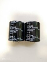
Next, max capacitor diameter is 35 mm. Previously I gave you wrong data and I appology for that. Distance among leads is 10mm. Use capacitors with snap-in soldering pins. It is impossible to use capacitors with screw terminals.
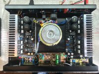
Also, having capacitors on-board is a huge advantage. They are placed very close to rails, almost on the leads of the output devices and may wuickly provide extra current when needed. Any additional wirings would add to unnecessary impedance.
PS but important: Observe the board between the power supply capacitors. There is fine star grounding which is important for achieving low noise floor. Therefore, keeping capacitors exactly where they are supposed to be is of paramount importance for achieving very low noise.
Last edited:
Hello to all.
Paraxod4, I agree with you, JCCON for the eyes of this Chinese clone. All sorts of Mundorfs are for McIntosh and Audionots.
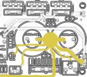
An oscilloscope is a useful tool, it was not for nothing that it took for nothing. I looked at the form of power supply of the preliminary cascade, and there ripples, you can see it below in the photo.
Measured on diodes (katode):

In kit 5mV.

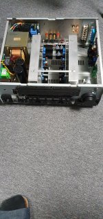
I decided to go extensively and increase the total capacitance of the test board. Now the total capacity is 80 000μF. I also laid a conductor with a cross-section of 4mm2 on the board from the OUT connector to the IN GND input, Now only my children can hear the fading quiet buzz. In principle, I am satisfied. It remains to test the power amplifier board and match it in volume with the preamplifier. I already wrote that the sound in acoustics sounds excessively loud at the beginning of volume control. Can someone suggest how to make it quieter by changing only the power amplifier circuit?
Paraxod4, I agree with you, JCCON for the eyes of this Chinese clone. All sorts of Mundorfs are for McIntosh and Audionots.
An oscilloscope is a useful tool, it was not for nothing that it took for nothing. I looked at the form of power supply of the preliminary cascade, and there ripples, you can see it below in the photo.
Measured on diodes (katode):
In kit 5mV.
I decided to go extensively and increase the total capacitance of the test board. Now the total capacity is 80 000μF. I also laid a conductor with a cross-section of 4mm2 on the board from the OUT connector to the IN GND input, Now only my children can hear the fading quiet buzz. In principle, I am satisfied. It remains to test the power amplifier board and match it in volume with the preamplifier. I already wrote that the sound in acoustics sounds excessively loud at the beginning of volume control. Can someone suggest how to make it quieter by changing only the power amplifier circuit?
Last edited:
Привет ВМК2002! (Eng: Hi VMK2002!)I also want to ask, what preamplifiers do the participants in the discussion use?
I'm glad you're making a huge progress.
I have Marantz CD/USB player but...
... I am sing a MBL6010D clone preamplifier which is great so I have two of them. One I have assembled from completely reputable components starting from bare board, another is Chinese "completed". Both are good.
Both are good, but I prefer using directly a DIY HiFi parallel PCM1794A decoder board DAC core board 24Bit 192kHz hooked to XU208 Daughter Card Decode Board Support 32BIT 384K ES9018 Decoding USB IIS. So I can stream quality audio recordings from PC.
Decoder board sounds much better than my Marantz CD/USB player.
Cheers!
That's the right decision. 4X10.000uF per channel is "just" enough but not enough if you want more. That is why I have experimented with adding external capacitance. It is possible to use an external power supply in series and leave all on-board capacitors. They are a precious asset because they are located in close proximity of the rails, almost on the leads of power transistors. Along with the built-in star grounding thisNow the total capacity is 80 000μF. I also laid a conductor with a cross-section of 4mm2 on the board from the OUT connector to the IN GND input, Now only my children can hear the fading quiet buzz. In principle, I am satisfied.
Thanks for your contributions to this discussion. I indeed appreciate that.
Regards!
Let me tell you more. Below you can see my recent THD+N measurements of smaller A60 with just 2X22.000uF per rail. Observe how low is noise floor. With capacitance multiplier it is much lower.
This measurement was with KSA992/KSC1845 transistors which aren't adequate according to my measurements. With CDIL 2SA970/2SC2240 the THD-N value is half lower-
Also observe THD measurements. The 2nd harmonic dominates whilst the 3rd is far below audible. Such a mixture of harmonic distortions makes this amplifier sound indeed pleasantly.
What is the minimum size of a radiator that can be used? There is a finned 200x70x30mm. Enough for each channel?
PCB size: 273*88mm.What is the minimum size of a radiator that can be used? There is a finned 200x70x30mm. Enough for each channel?
Add to that enough room for output transistors. Also, when biased into A class there is a great deal of heat.
I am using Fischer Electronics SK 56 L=300mm, H=200mm, W=40mm K=0,31W/K
- Home
- Amplifiers
- Solid State
- A60(+) Amplifier. Build this?