Berlusconi Everything is correct the first switching on only through the lamp  vmk2002 Read carefully and everything will work out.🙂
vmk2002 Read carefully and everything will work out.🙂https://aliexpress.ru/item/40000632...7.0&pvid=24cd2e02-1ae8-468e-a546-6ec7ecc8d857 I bought these, just not from this seller. All came whole, the quality is excellent, they do not break under normal pressure.
I think you're right. Just observe the 3rd photo in post #58. There is solder on five holes without terminals. At the first glance one might think that it is used board but it isn't. Observe that "Input" terminals are not covered with solder. This indicates that the board was connected to transformer just for testing purposes. But I still wonder why they did not solder terminals? Terminals cost virtually zero..... everything will work out.🙂
I think the board was tested after soldering.

Last edited:
I am glad to welcome fans of audio equipment! Berlusconi is authorized to inspect boards prior to shipment. At least, the Chinese assured me that he checked the boards and adjusted something there for the amplification class A. Today I ordered screens (pots) for transformers from them and asked them to report the missing terminals to the package. I will wait for the packages now. In the meantime, I put the boards on paper and transferred the holes for the clamping of the transistors and fastening the boards to it. I think then I will cut the paper, glue it to the radiator and outline the holes. It is not yet clear how to connect the indicators with arrows, whether an intermediate board is needed between the power amplifier and the indicators. Don't dear audiophiles have a complete set of this amplifier to clarify my question?
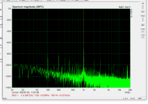
I have proceeded with square wave response analysis. It would be pointless to show a series of perfect rectangles indicating adequate square wave response within the entire audible range. Instead, the figure below shows just the initial part of the response to 50Hz square wave. The figure shows rise within 1.25uS followed by constant peak amplitude.
Your measurement seems done at 5V/div so slew rate must be around 30/1.25=24 V/uS right? Have you managed to sim or measure THD at 1kHz and 20kHz respectively? Can put some more measurement data please? Did you manage to sim phase margin, open loop stability etc?
Last edited:
That's correct Erlend, but overall, compared to several highly praised amplifiers, A60+ sounds awesome and measurements are exceptional.Have read some claim these boards have hundreds of v/us. But that's not true.
@terranigma
Right now I have one channel on the bench and will produce new measurements.
I was initially planning to increase capacitance signifficantly above the 4X10.000uF but that remained just a plan. Measurements of noise without signal at input were astonishing. Just few mVrms. I'm not sure what is the real reason for so low noise but it must have to do with very compact design. Output from rectifier section is virtually directly connected to the rails. There is no need for decoupling capacitors because power supply is practically on rails and power supply ground is virtually output ground. Power devices are fed directly from the power supply. In addition to that power supply utilizes very fast Schotky diodes.
I have also tried adding extra 8X22.000uF, but reduction of noise was about 1mVrms. I decided to leave the boardwith "just" 4X10.000uF. More than good enough for practical purposes.
Cheers.
Last edited:
Sorry for the delay. I didn't want to repeat myself or provide what's already known.Your measurement seems done at 5V/div so slew rate must be around 30/1.25=24 V/uS right? Have you managed to sim or measure THD at 1kHz and 20kHz respectively? Can put some more measurement data please? Did you manage to sim phase margin, open loop stability etc?
First, one clarification: I do not simulate, I measure. Not because I couldn't but because I think I really understand the purpose of simulation.
I was waiting for my new toy: XONAR U7 MkII sound card but was curious what can I do with my built-in sound card: 7.1 CH HD Audio (Realtek ALC1220 Audio Codec) in my Asrock Z270M Extreme4.
The results were encouraging.
I have used signal generator of my oscilloscope and connected it directly to the input of A60+ amplifier 1Khz, 600 mV p-p. As a load I have used three 22Ohm 100W resistors in parallel. In parallel to the load I have connected a simple voltage divider constructed on a piece of prefboard. Wiring was really done sloppy, in haste.
After some input calibration I have got the result below.
Take into account that this was my first THD-N measurement, on a crappy hardware and in haste. Yet, according to FTC, the result can be conditionally considered as HiFi. (...less than 0.02% total harmonic distortion...).
For the next set of measurements I intend to revamp the hardware.
Regards
Attachments
@Berlusconi, thank you for your efforts in order to show some real world performances. I mentioned sims regarding phase and gain margin plots only since this department is not going to be easy for plot. Additionally, simulation helps to optimize compensation scheme in order to improve slew rate performance.
Next time, can you give more precise info on measurement conditions please? I think that input level has not a significant importance on THD measurement. Output swing level and load (which is 22/3) has much more importance.
Next time, can you give more precise info on measurement conditions please? I think that input level has not a significant importance on THD measurement. Output swing level and load (which is 22/3) has much more importance.
Last edited:
Ah, I see.
I have never had ambition to tweak electronic circuits because I admit that my knowledge is too modest. Instead, I use measurements to identify which candidate boards have characteristics worthy effort to be put into a pretty chasis. This one has passed: it sounds good, it has more than adequate measurements. What else anyone may want? I ain't no "audiofool", just an enthusiast who wants to enjoy playing with this fine hobby.
Already initial sloppy measurements indicate its quality. Now, I just want to know how good it really is and to play a bit more, nothing serious, just my personal curiosity. I am a professional in other scientific field: chemistry.
Regards
A60+ Connection PCB VU
🙂 Hello. I ask for help. I figured out the soft start board. But I can’t figure it out with the dial gauge control board. Tell me how to connect this board to indicators? There are no markings on the indicators except as I understood +/- backlight supply. It is also not clear where to send a signal to the input of the IN. I attach a photo:
🙂 Hello. I ask for help. I figured out the soft start board. But I can’t figure it out with the dial gauge control board. Tell me how to connect this board to indicators? There are no markings on the indicators except as I understood +/- backlight supply. It is also not clear where to send a signal to the input of the IN. I attach a photo:
Attachments
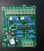
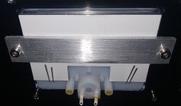
I figured it out a little more. The thin pins on the indicators to the left and right of the marked "+" and "-" are the backlight LEDs. I checked by measuring the resistance between these leads and they lit up. It remains to understand where and what voltage to supply power to the indicator control board.
Bought from weiliang audio Official Store. The Chinese did not answer my connection question. They do not have a connection diagram on the site.
https://aliexpress.ru/item/1000004729007.html?spm=a2g0o.store_pc_allProduct.8148356.1.32553440lC3f9p
https://aliexpress.ru/item/1000004729007.html?spm=a2g0o.store_pc_allProduct.8148356.1.32553440lC3f9p
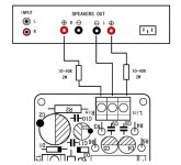
Now my only question is how to connect this board to the output of the power amplifier. Each channel is powered through a separate transformer with two windings with a midpoint. Therefore, I cannot figure out how to connect "-" from the outputs of the power amplifier to this board, since this board has only one "-" input and two "+" inputs for the left and right channels. There is of course an option to connect to the input RCA connectors, but I think that there will be distortions of the input signal of the power amplifier.
Everything is there, do not worry, carefully study the photos below on the site, if you give prompts, you will not understand anything, you have to try to delve into it yourself, otherwise there will always be a lot of questions.😉🙂
Look here: 😉
https://www.diyaudio.com/forums/analog-line-level/316012-correct-connect-vu-meter.html#post5273315
Is your amplifier functional now?
https://www.diyaudio.com/forums/analog-line-level/316012-correct-connect-vu-meter.html#post5273315
Is your amplifier functional now?
Hello. While I am waiting for the "pots" - the transformer screens, and thinking about the location of the soft-start boards and the PCB for controlling the indicators. I didn’t think of anything else how to raise the transformers on the bolt racks, and place these boards under them. Now I am preparing these "floors" and at the same time collecting information on connecting all the boards. I also want to add a transformer and rectifier to power this indicator board and power the indicator backlight LEDs. By the way, thanks for the link, I'm reading it now.
The boards sold on aliexpress have 2 types of signal connection to the indicator control board. Option 1 - directly from a sound source (CD, DVD). Everything is clear with him. Left / right channel and GND. Option 2 - through a 10kOhm ... 40kOhm resistor from the output terminals of the power amplifier ("+") to the input of the indicator control board (L_IN / R_IN). And where to start at the GND input? After all, the left channel is not galvanically connected to the right channel, so the power amplifier channels are powered from different transformers (2 separate transformers, one per channel, each transformer has 2 windings with a midpoint). This is the only misunderstanding so far, since I want to use option 2.
Attachments
Do not connect it to the input otherwise it will compromise sound quality. From the attached photo it apears that the board has overvoltage protection. Correct me if I am wrong but there is UPC1237 in the middle of the VU board. Also the amplifier has speaker protection. You have to connect it properly and adjust sensitivity on potentiometers which are located at the board.🙂 Hello. I ask for help. I figured out the soft start board. But I can’t figure it out with the dial gauge control board. Tell me how to connect this board to indicators? There are no markings on the indicators except as I understood +/- backlight supply. It is also not clear where to send a signal to the input of the IN. I attach a photo:
However, try to test it on something cheaper, some old PC speaker or test it with batery and voltage divider to prevent overvoltage.
PS: I think that's really simple. Could you please provide photos of the board from different angle and read what is written on that long black bar in the middle of the board. I suspect it is UPC1237.
Last edited:
- Home
- Amplifiers
- Solid State
- A60(+) Amplifier. Build this?