Finally got enough other (non-tube, non-electronics) projects out of the way such that SWMBO is allowing expenditure and effort in smoke making.
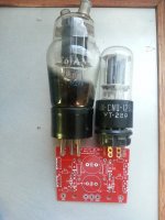
I got a bunch of VT61A HF triodes a while back - very old WWII surplus. These are a cute-as Mickey Mouse tube used as finals in the radio sets in Spitfire aircraft. Who could resist? Closest data I could get was RK34 which is electrically identical, different base.
So the plan is for a 'sl7 LTP buffered by Pete's clever little circuit and swinging the required 100v p-p into the VT61A driving it as close to AB2 as I can get without sounding horrific.
OPTs are probably going to be Edcor 15w open frame jobs with power coming from Edcor as well. Optional OPTs are some nice vintage NOS 8k:8 units built to go into high end local EL84 pp designs.
The design goals are stringently non-audiophile. Sure, it has to sound acceptable but the main goal is something looking cool (shallow Hal is me) in a steam-punkish sort of way, not the standard path EL84, with an interesting mix of old and new-ish tech.
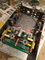
A very standard design kwila wood frame topped with an aluminium plate is the chassis.
Speakers are a very simple early '70s vented box design with paired 16 ohm 8 inch drivers in parallel in each box. Not at all peaky or hard to drive, but also not SOTA.
Source is a Sumsung HDTV, processing (badly) DVD/CD, Spotify from a no-name Android tablet via HDMI, and a mix of mp3-esque players. I am going to be all rash and assume standard 2v source output. Eventually a pre-amp (likely a simple versions of SY's Heretical) will do front end duties and liberate me from the TV as preamp.
We'll forget about the turntable atm since that just complicates things further.
Comments and advice encouraged as we go - this may take some time so sit back and don't hold your breath...
I got a bunch of VT61A HF triodes a while back - very old WWII surplus. These are a cute-as Mickey Mouse tube used as finals in the radio sets in Spitfire aircraft. Who could resist? Closest data I could get was RK34 which is electrically identical, different base.
So the plan is for a 'sl7 LTP buffered by Pete's clever little circuit and swinging the required 100v p-p into the VT61A driving it as close to AB2 as I can get without sounding horrific.
OPTs are probably going to be Edcor 15w open frame jobs with power coming from Edcor as well. Optional OPTs are some nice vintage NOS 8k:8 units built to go into high end local EL84 pp designs.
The design goals are stringently non-audiophile. Sure, it has to sound acceptable but the main goal is something looking cool (shallow Hal is me) in a steam-punkish sort of way, not the standard path EL84, with an interesting mix of old and new-ish tech.
A very standard design kwila wood frame topped with an aluminium plate is the chassis.
Speakers are a very simple early '70s vented box design with paired 16 ohm 8 inch drivers in parallel in each box. Not at all peaky or hard to drive, but also not SOTA.
Source is a Sumsung HDTV, processing (badly) DVD/CD, Spotify from a no-name Android tablet via HDMI, and a mix of mp3-esque players. I am going to be all rash and assume standard 2v source output. Eventually a pre-amp (likely a simple versions of SY's Heretical) will do front end duties and liberate me from the TV as preamp.
We'll forget about the turntable atm since that just complicates things further.
Comments and advice encouraged as we go - this may take some time so sit back and don't hold your breath...
Last edited:
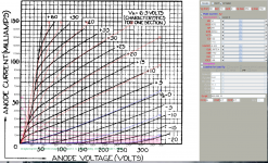
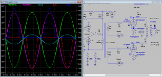
Here LTSpice model for VT61A I painted, not terribly accurate, but doable, grid current included.
Attachments
Last edited:
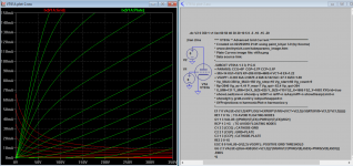
Because grid current is not on the same plot, I have to readjust it here is more accurate model.
**** VT61A ** Advanced Grid Current **********************************
* Created on 02/29/2016 22:27 using paint_kit.jar 3.0
* Model Paint Tools: Trace Tube Parameters over Plate Curves, Interactively
* Plate Curves image file: vt61a.png
* Data source link:
*----------------------------------------------------------------------------------
.SUBCKT VT61A 1 2 3 ; P G K
+ PARAMS: CCG=6P CGP=2.7P CCP=2.1P
+ MU=14 KG1=1575 KP=206 KVB=4609.4 VCT=0 EX=1.22
+ VGOFF=-0.291 IGA=0 IGB=1 IGC=23.2 IGEX=1.26
* Vp_MAX=350 Ip_MAX=150 Vg_step=10 Vg_start=60 Vg_count=9
* Rp=2840 Vg_ac=1.41 P_max=7 Vg_qui=-63.4 Vp_qui=204
* X_MIN=131 Y_MIN=124 X_SIZE=825 Y_SIZE=719 FSZ_X=1605 FSZ_Y=1003 XYGrid=true
* showLoadLine=n showIp=y isDHT=n isPP=n isAsymPP=n showDissipLimit=n
* showIg1=y gridLevel2=y isInputSnapped=n
* XYProjections=n harmonicPlot=n harmonics=y
*----------------------------------------------------------------------------------
E1 7 0 VALUE={V(1,3)/KP*LOG(1+EXP(KP*(1/MU+(VCT+V(2,3))/SQRT(KVB+V(1,3)*V(1,3)))))}
RE1 7 0 1G ; TO AVOID FLOATING NODES
G1 1 3 VALUE={(PWR(V(7),EX)+PWRS(V(7),EX))/KG1}
RCP 1 3 1G ; TO AVOID FLOATING NODES
C1 2 3 {CCG} ; CATHODE-GRID
C2 2 1 {CGP} ; GRID=PLATE
C3 1 3 {CCP} ; CATHODE-PLATE
RE2 2 0 1G
EGC 8 0 VALUE={V(2,3)-VGOFF} ; POSITIVE GRID THRESHOLD
GG 2 3 VALUE={(IGA+IGB/(IGC+V(1,3)))*(MU/KG1)*(PWR(V(8),IGEX)+PWRS(V(8),IGEX))}
.ENDS
*$
Am I reading you right that you are using 2 voltage gain stages in your proposed amp? It doesn't seem necessary to me if one of the voltage gain stages is a 6sl7 and you are only driving el84s. Maximum P to P voltage for full output for an el84 is about 22 to 30 volts probably before feedback. Double that to give 6 db global feedback potential. More than that and you have the potential to decrease the spaciousness of the sound presentation.
The mu of a 6sl7 is 70 so typical amplification with an LTP pair will be 25 to 32 or thereabouts. A 2 volt rms input from the usual line sources is 5.6v p-p. Multiply the nominal 25 gain times that input and you have 140v P-P. Unless you're using some very strange topology that requires huge amounts of feedback it seems like the vt61a is redundant. But if you really like it then maybe you can just frame it and put it on the wall by itself.
The mu of a 6sl7 is 70 so typical amplification with an LTP pair will be 25 to 32 or thereabouts. A 2 volt rms input from the usual line sources is 5.6v p-p. Multiply the nominal 25 gain times that input and you have 140v P-P. Unless you're using some very strange topology that requires huge amounts of feedback it seems like the vt61a is redundant. But if you really like it then maybe you can just frame it and put it on the wall by itself.
Ok, I reread your first post and I guess you're using 1 voltage gain stage and using the spitfire tubes as the outputs. That makes more sense. Never mind.
Ok, I reread your first post and I guess you're using 1 voltage gain stage and using the spitfire tubes as the outputs. That makes more sense. Never mind.
you got it!
I'll be following with interest. My experience with circuits such as you're planning is that significant 'crossover' distortion occurs as the grids go positive, apparently due to non-zero driver output impedance.
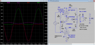
I haven't yet sim a driver that drive the grid positive. It appears the input impedance is around 3K above zero, if input drive is 25V, this is over 8mA grid current. At -25V bias, with 25V input, there is no crossover distortion seen at the output only just over 2W rms.
Attachments
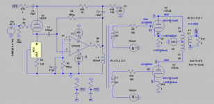
Oh yes, I remember now I sim OpAmp before, it's IT driven A2, so I just plug in and the output has increased to almost 10W (from previous 2W). The driver on left is a version of SuperTriode now standalone, then again can be tied to plate of output if we build 2 independent drivers. How to direct couple the driver without an IT?
Attachments

Last edited:
Are you referring to Pete's MOSFET A2 buffer or something else?I'll be following with interest. My experience with circuits such as you're planning is that significant 'crossover' distortion occurs as the grids go positive, apparently due to non-zero driver output impedance.
Funnily enough I am building just such an amp at the moment. I have used Petes compactron triple triode design and also his fet follower design both slightly modified to meet my needs. The outputs are a 2C34 on a different base. I wont say its name as it is rather rare but it seems identical to 2C34. on the breadboard I used some 8K Toei transformers and it sounded great with no crossover distortion at all.
Cheers
Matt
Cheers
Matt
Attachments
Are you referring to Pete's MOSFET A2 buffer or something else?
My latest experience was with a BJT emitter follower, biased around 5mA, driven from a voltage amp stage with about 24K output Z, and driving the grids of a pair of 13GB5s to about 70mA peak. I reckon net driver output Z of roughly 245R. Observed distortion products exhibited a very clear transition to sharp edges coincident with grid current inception. From this evidence, I suspect that grid power drive circuits must have output Z at least an order of magnitude lower to qualify as "high-fidelity."
Okay, I see the error in my ways... If MOSFET source follower output Z is 1/gm, then Millett's design should have Z out below one ohm. MUCH better than a simple BJT follower in this application. I'll try it in my own circuit before long.
Last edited:
I think Pete Millet's A2 circuit boards are a bargain and well worth the money. But I'm not so sure I would set mine up the way he is. He is using approx 25ma going through the mosfet. And he is also specifying a humongous heatsink. I'm working on a design using about 5 ma running through the mosfet, and though I don't have actual results yet for my application I think it will be plenty.
It you use Pete's design I would lower the Source/Drain voltages and lower the current too. I wouldn't be surprised if you could lower power dissipation then by 5 to 10x. I've simmed my design that way (only driving el84) and power dissipation is 1 watt or less per side of the push pull. I'll just be using average to small heatsinks underneath the chassis. I think you might be surprised if you sim it how much more power you can get out of a PP for most tubes with very little power running in the Mosfet driving the A2. It's counterintuitive.
It you use Pete's design I would lower the Source/Drain voltages and lower the current too. I wouldn't be surprised if you could lower power dissipation then by 5 to 10x. I've simmed my design that way (only driving el84) and power dissipation is 1 watt or less per side of the push pull. I'll just be using average to small heatsinks underneath the chassis. I think you might be surprised if you sim it how much more power you can get out of a PP for most tubes with very little power running in the Mosfet driving the A2. It's counterintuitive.
I guess I should clarify that the simmed power dissipation mentioned only referred to power dissipation of the mosfet by itself. You might get a lot more power dissipation through the output tubes depending on how you set up the bias point and how far you drive the grid into positive territory. Farther into positive territory also puts much greater power dissipation on the mosfet. If you use tubes that don't normally use any power going into the grid in normal operation one might be surprised how little power dissipation is required in the mosfets for major overall improvements.
That may well work on EL84s but these little babies (VT61A) drag around 15ma grid current at max output, so a 5ma standing current is unlikely to do the biz.
Just to be clear, the buffer boards I've got coming from Pete are CCS loaded MOSFETS (as exeric notes), not op-amps as I linked at the top of this page.
Just to be clear, the buffer boards I've got coming from Pete are CCS loaded MOSFETS (as exeric notes), not op-amps as I linked at the top of this page.
Okay, I see the error in my ways... If MOSFET source follower output Z is 1/gm, then Millett's design should have Z out below one ohm. MUCH better than a simple BJT follower in this application. I'll try it in my own circuit before long.
Great, thanks for the clarification - it's the BJT follower that has the higher output Z. Whew...🙂
Thanks Pete - 2013 technology is looking forward to working with WW2 tubes
Attachments
Last edited:
- Status
- Not open for further replies.
- Home
- Amplifiers
- Tubes / Valves
- A2 p-p with Millett driver