

well, hasn't time marched on...
Lots of scribbling on bits of foolscap (how appropriate is THAT name) has led me to the current near- finished schematic and specs. Here goes for comment and constructive criticism.
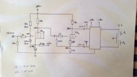
I follow the design path of Miles Prower, SY and others who start at the end, so the opt is a 8k:8. In fact, it is a 100v 30W line transformer. Told you I was cheap!
The VT61a will be running in Class A2. 300v at the anodes, and obviously fixed bias at 0v, just enough resistance in the cathode to measure current through each tube.
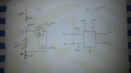
Pete's A2 driver circuit direct couples to the VT61a grids and provides 40vpp of swing. 20ma standing current in the driver means the 12-ish ma grid current at the +20v excursion will be no problem. The driver circuit is supplied 35-0-35 from a regulated source - nothing special, LM317/LM337 devices will look after keeping the voltages honest. A bias supply (resistor and LED string powered from the same 35-0-35 source) provides +4v bias to the A2 driver.
Back further we find the driver is cap coupled to a pretty standard concertina splitter built around the triode section of a ECF802.
Back one more step we arrive at the pentode section of the ECF802 running in pentode, g2 at 100v with simple zener regulation. Gain here is around 70 leaving scope for some feedback to be applied. Thanks Merlin for the quick and dirty design technique in the pre-amp book.
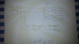
Power supply is slightly unusual and is built to use iron already at hand. A remote 230v/24v 120VA transformer will front as an isolation device meaning the entire amp itself is separated from the line circuit.
An umbilical brings the 24VAC to the amp where it supplies two separate 12/230 50VA transformers with the 12V primaries in series. Yes yes, bad practise, but the entire amp is in Class A so a steady stream of like-minded electrons in roughly equal quantities will circulate in each transformer and so maintain roughly equal primary loading. CRC smoothing followed by a HV regulator look after providing 300v for the B+, and another RC stage drops the supply to 250V for the B++ supply to the ECF802
A separate voltage trebler turns some of the 24VAC into 100VDC which is then split and regulated to provide +35V and -35V with a virtual 0v in between. It only needs to provide around 120ma total so I can afford a bit of impedance and other not-very-audiophile shenanigans in this bit.
Still haven't figured how to get a reasonable heater supply out of the 24VAC supply, but thats minor.
Pete has graciously cast his eye over the bits that directly impact on his reputation and issued a cautious "ok then". Anyone else see any howling errors?
I do think that with 300V on the anodes of the outputs you will need -15V on the grids.
http://www.r-type.org/pdfs/rk34.pdf
Cheers
Matt
http://www.r-type.org/pdfs/rk34.pdf
Cheers
Matt
If I wanted to go into Class B, yes. In this case, I'm going Class A2.
The VT61A (RK34) is capable of over 30v positive grid voltage, and at 300v on the anode, cut-off the other way is just after -20v. No point driving it any lower than that... unless I wanted AB2.
The VT61A (RK34) is capable of over 30v positive grid voltage, and at 300v on the anode, cut-off the other way is just after -20v. No point driving it any lower than that... unless I wanted AB2.
I picked up some Mullard ECF802's on Trade Me for cheap and will be using them for a similar front end. I have done Spice models for both sections if you want them.
Spice is nice, but I only understand pencil...
I really should spend some time getting to grips with modelling in spice. Too much other stuff going on to be bothered atm.
Cheers for the offer though!
I really should spend some time getting to grips with modelling in spice. Too much other stuff going on to be bothered atm.
Cheers for the offer though!
Alrighty, physical layout.
The audio signal circuit is going into a bog-stock kwila hardwood-framed aluminium topsheet design. There is space for SOME of the power supply circuit, but probably not all.
Power supply is a 110W 230/24v transformer which will supply two 230/10-12v 50VA transformers running back to front and in series. A 35-0-35 DC supply is generated from the 24VAC.
Heaters I have two options - use the 24VAC to generate this as well, although I suspect I am going ot be up against hte limits of the main transformer's VA rating. Alternatively, I an use a separate 230/12 50VA transformer for this.
So, how much of this to stick in the planned external power supply? At present, I'm thinking keep all the AC stuff external, and send the raw DC supplies to the amp with regulation, distribution and bypass caps etc all happening there.
This means the umbilical has to carry a 330VDC with around 5v ripple, a 50-0-50VDC with negligible ripple, and a 12VDC with probably 1.5V ripple.
OR - do it ALL in the external supply box with smoothed and regulated supplies sent to the amp where there is just the capacitance required to maintain nice play.
Any thoughts? And any suggestions for umbilical connectors that are suitable for these voltages?
I picked up some Mullard ECF802's on Trade Me for cheap and will be using them for a similar front end. I have done Spice models for both sections if you want them.
I'll be very happy to have those models 😀
How are you getting on with this project? I've knocked up a simple common cathode gain stage, Cathodyne PS followed by two cathode followers using Russian 6H8C dual triodes. I'm only getting about 3w - OPT Z pri 8k. The OP isn't clipping, but has crossover distortion.
The 2C34's are biased at -15v using a bench PSU at present. At rest they draw 38mA Ik which is high, loadline suggests under 20mA quiescent. Cathode current goes DOWN to 28mA full OP.
The drivers are capable of 110v P-P, G - G. Something odd is going on as at full whack the grids drop to 26v DC. Conclusion, not the easiest valves to drive but will persist. The front end circuit was knocked up quickly and needs looking at. I'll check out your method of driving the OP valves.
Andy.
What's your b+?
I built a PP amp w/ 3c24 several years ago, but it never got off the breadboard and then I got a baby and shelved it.. My end goal was parallel push pull, but that's just crazy.. 3 amp filaments plus the regulators burning power was about 225 watts lost to heat and light per channel!
I built a PP amp w/ 3c24 several years ago, but it never got off the breadboard and then I got a baby and shelved it.. My end goal was parallel push pull, but that's just crazy.. 3 amp filaments plus the regulators burning power was about 225 watts lost to heat and light per channel!
B+/HT is 330v which is a tad high as 2C34 Va max is 300v. I found HF oscillation on the 2C34 anodes and need to re-do the cathode followers.
Will start a thread at some point.
A.
Will start a thread at some point.
A.
- Status
- Not open for further replies.
- Home
- Amplifiers
- Tubes / Valves
- A2 p-p with Millett driver