My solution to this in the 833 amps was 2 power switches. The first paddle switch must be thrown for the second pushbutton switch to operate. First switch powers the driver stage, fixed bias and the 833 filament. After a warmup I press the HT power pushbutton which ramps up the 2.3kV HT via a soft-start circuit.The startup sequence in direct coupled tube amps can become quite nasty if everything isn't done right. The best case should be if the output tubes are biased to cutoff until the filaments are fully heated and the HT is up. The worst case would be a high positive voltage on the grid, but too much negative voltage would also be dangerous to the tubes.
Quite an amp you have there, Magz! Respect!
My latest idea to get a controlled startup is to use 6,3V damped diodes (6AU4GTA) as HT rectifiers, heated by a transformer with a slightly higher voltage ( I ordered one 7V and one 8V heater transformer to run som practical tests) and a bit of resistance in series with the heaters to get some extra delay and a slower ramp-up. This should be slow enough to let everything else settle before the tubes see any high voltage and the slow ramp-up hopefully prevents any nasty voltage peaks into the power tube grids during startup.
My latest idea to get a controlled startup is to use 6,3V damped diodes (6AU4GTA) as HT rectifiers, heated by a transformer with a slightly higher voltage ( I ordered one 7V and one 8V heater transformer to run som practical tests) and a bit of resistance in series with the heaters to get some extra delay and a slower ramp-up. This should be slow enough to let everything else settle before the tubes see any high voltage and the slow ramp-up hopefully prevents any nasty voltage peaks into the power tube grids during startup.
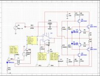
A conceptual drawing of my latest idea. Ignore the lack of grid/gate stoppers, current measurement resistors, protection diodes etc:

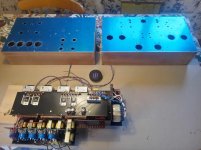
Got my transformer covers from Piemme Transformatori today, time to start looking at the layout. Opinions are most welcome!


Looks-wise, I like the warm glow of tubes right up front on the top plate. I also like to run the signal from the preamp to the front side of the amp to keep the signal path short and minimize noise pickup from the power supply.
See the pic on the previous page as an illustration.
See the pic on the previous page as an illustration.
I agree, the tubes should be as visible as possible from the front (although you have to look down into the anode system from exactly the right angle to see any glow in the 6S4S tubes). I'll probably have to buy a larger sheet of aluminium to be able to make a good layout. The power supply will be in separate, equally sized chassis which will be very crowded with transformers and chokes.

Thanks. The amp chassis is the easy part, I'm waiting for 20+ kilograms of transformers and chokes that must be shoehorned into another similar power supply chassis. Most of them are open-frame types that will be mounted below the top plate.
I mentioned a big box of Hammond iron a while back (almost two months ago actually) and today it arrived:

Unfortunatley the guys at Don Audio doesn´t seem to take packaging too seriously, it was just blind luck that nothing had fallen out through the big cracks in the box and that only one of 20+ items was damaged to the point that I will need to ask for a replacement😒
Fortunately, the damaged transformer is one of two different heater transformers that I ordered for the rectifier tubes and I had already decided to use the other one.
I might have cooked something up here that could solve several problems at once: The startup sequence in direct coupled tube amps can become quite nasty if everything isn't done right. The best case should be if the output tubes are biased to cutoff until the filaments are fully heated and the HT is up. The worst case would be a high positive voltage on the grid, but too much negative voltage would also be dangerous to the tubes.
In this circuit we have a voltage divider that sets the negative bias voltage for an N channel Mosfet, which operates as a simpe voltage regulator with a low Z output. The "cold" end of the interstage transformers is connected here, and the "hot" end of the winding goes to the grid of the cathode follower triode.
During startup, with cold tubes, we should have current flowing from ground through the mosfet and on through the IT winding, the protection diode and the 15k resistor. As long as there is current flowing through the transformer winding the resulting output voltage should be a few volts more negative than the -70V or so that we have at the Mosfet's source. Once the cathode follower warms up and starts conducting the output voltage will rise to its preset value and the protection diode will become reverse biased.
Unless I've missed something, of course... 🙂
To avoid unnecessary confusion: I mentioned the idea of using interstage transformer wired as chokes as cathode loads for the driver tubes earlier. In this circuit the 15k resistor and the much higher negative rail voltage replaces the choke. The IT winding in the schematic is (one half of) the secondary winding of an interstage transformer that actually operates as such by feeding the cathode follower(s) signal from the input stage. View attachment 1165181
Its late and im tired. Buf if the grid starts attracting electrons, and the interstage is just a voltage source between the bias supply and grid. doesnt that mean that this circuit should sink current into the negative rail instead of sourcing it from ground? In other words you may need to reverse the circuit with a pull-up resistor from ground to the bias point, and a P-channel device.
The reason im asking is that im working on a bias servo for exactly this purpose: biasing up an interstage. And my simulation shows current draw from the negative rail. Ive modeled grid current as just a diode+resistor on the secondary to GND
Edit, im dead wrong. I will keep the comment up for the perhaps interesting circuit.
Attachments
Last edited:
- Home
- Amplifiers
- Tubes / Valves
- A2 experiments