Hi,
While waiting for some Lundah OPTs and ITs to arrive for my next project, I´ve spent a couple of nights playing with the tubes (6S4S, soviet 6B4G) and some transformers I already have to see how the tubes behave when pushed into class A2.
The basic setup is a PP output stage with 2* 6S4S running at 290V 55mA with a 7k7 output transformer, giving ~7,5W in class A1 (22k grid stoppers where used to ensure no grid current could interfere with the measurements).
The driver stage was a triode wired 6AV5GA sweep tube running at 240V 50mA into a Lundahl LL1671/50mA interstage transformer wired as 2 : 1+1, doing double duty as a phase splitter. The transformer secondary CT was connected to a negative voltage buffered with a Mosfet to provide a low impedance bias supply.
With the grid stoppers removed, this tube/IT combo was able to push the 6S4S grids some 15-20V above zero, resulting in almost 13W out.
Very interesting so far, but only below a few kHz. At higher frequencies I get the impression that the sudden current draw from the grids triggers some bad behaviours in the transformer. Due to my vintage test equipment I can't tell exactly what's happening but I get the impression that the secondaries are ringing.
Changing to an LL1660 IT (2,25+2,22 : 1+1) driven by a balanced pair of 12B4A shoved pretty much the same behaviour. Changing to higher Rp driver tubes (2* CV1135, ~6J5) didn't do much for the presumed ringing but provided inadequate A2 drive current.
Am I doing something wrong or is IT coupling a dead end when it comes to class A2 operation?
The point of using It coupling is the low secondary impedence for a2 opperation. Try the bandwidth before going into a2 and using it for phase splitting is far from ideal due to the construction of the transformer itself and the resultant phase shifts between windings. Most reputable tube transformer manufactures/japanese dont make them. Also lundhal you get what you pay for.
Yes, I guess it's a tall order for a transformer to simultaneously act as phase splitter and plate load for the driver while providing both large voltage swings and current peaks to te grids. Still, nice to see that the russian 6B4G operates quite well in A2.
I built a PP A2 design from Electra-Print that uses an interstage transformer. But it has a chip front end. As mentioned IT''s work. Others use a cathode follower front end instead.
Keep at it.
Keep at it.
A2 with chip front end and interstage transformer, that's exotic! I think I've seen such designs on this forum, by Pete Millett and others.
For the moment I've given up on using transformers to drive the output tubes (there are probably other, much more expensive transformers that could do a better job) so the next attempt will be with direct coupled cathode followers. Mosfets would be better but I'm a bit nervous about potentially dramatic events during startup, not to mention what would happen if the fets fails as shorts.
My 807 PP monoblocks uses the pentode sections in ECL84/6DX8 as followers and they work surprisingly well, pushing a pair of triode wired 807s into 13W at less than 300V plate voltage. The followers are loaded with a center tapped choke where the CT connects to a negative rail. This arrangment works quite well but requires fairly closely matched tubes since the bias cannot be individually adjusted.
I have this idea about using my Ll1660 10mA ITs as cathode chokes in a similar but slightly more sofisticated circuit: The winding sections on each bobbin could be connected in series to make two magnetically coupled but galvanically separated inductors, allowing the bias to be adjusted separately for each tube.
Driver tube candidates would be 12B4A, 6N6P or 6E5P as I have several of each.
Well, you're past my pay grade. Thank you for showing your next schematic. Hope to learn from your experiments. Regards, HeyBill
I might have cooked something up here that could solve several problems at once: The startup sequence in direct coupled tube amps can become quite nasty if everything isn't done right. The best case should be if the output tubes are biased to cutoff until the filaments are fully heated and the HT is up. The worst case would be a high positive voltage on the grid, but too much negative voltage would also be dangerous to the tubes.
In this circuit we have a voltage divider that sets the negative bias voltage for an N channel Mosfet, which operates as a simpe voltage regulator with a low Z output. The "cold" end of the interstage transformers is connected here, and the "hot" end of the winding goes to the grid of the cathode follower triode.
During startup, with cold tubes, we should have current flowing from ground through the mosfet and on through the IT winding, the protection diode and the 15k resistor. As long as there is current flowing through the transformer winding the resulting output voltage should be a few volts more negative than the -70V or so that we have at the Mosfet's source. Once the cathode follower warms up and starts conducting the output voltage will rise to its preset value and the protection diode will become reverse biased.
Unless I've missed something, of course... 🙂
To avoid unnecessary confusion: I mentioned the idea of using interstage transformer wired as chokes as cathode loads for the driver tubes earlier. In this circuit the 15k resistor and the much higher negative rail voltage replaces the choke. The IT winding in the schematic is (one half of) the secondary winding of an interstage transformer that actually operates as such by feeding the cathode follower(s) signal from the input stage.
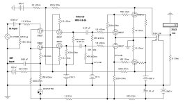
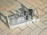
One of my experiments in Class AB2, CF driven PP 6V6s in 2005. 26 watts at clipping on a 340V lab supply.
Just a plain Jane Hammond 125E OPT. PP differential cascode front end, And an odd internal NFB connexion.
No expensive or exotic parts at all.👍
Just a plain Jane Hammond 125E OPT. PP differential cascode front end, And an odd internal NFB connexion.
No expensive or exotic parts at all.👍
Attachments

Before abandoning the "IT driving the grids directly" circuit try loading the full secondary with a resistor. Many IT's will ring at the transition point where the load goes from essentially the miller capacitance (A1 or AB1) to a low impedance as the grids start to draw current (A2 or AB2). Ringing is also common when the load transitions from low impedance to mostly miller capacitance The resistor value will need to be tweaked to calm the transformer. If the transformer secondary has a fairly high DCR it may not be suitable for A2 or AB2 since there will be drive voltage dropped across the DCR as the driven tube or tubes transition to A2 or AB2. .
I've been reading a lot about interstage transformers lately and loading the secondaries with resistors or Zobel filters seems to be a hotly debated topic.
One person is worried about anomalies in his IT coupled amp, someone suggests that loading the secondaries with resistors might help and minutes later a flock of drooling audiophiles arrive with anxious comments about how loading transformers down will kill the sound😀
My theory is that the ringing adds flavour to otherwise dull sounding amps...
I did however add resistors when I was running the 6AV5 - LL1671 combo but didn't see much difference on the scope. I'll try again later with different resistor values and RC-snubbers. The most problematic part is when the grid voltage goes back below zero into (almost) infinite impedance.
I'll return to the transformers after trying the cathode follower cct in my post above, I still have a week or two to mess around before the transformers that I actually bought for this project will arrive. I'm a bit impressed that the 6AV5 SE driver managed to push a PP pair fully into A2 with only a transformer as phase splitter, and the brutalistic approach is certainly attractive.
matejsirk: Interesting schematic, looks like a PP DRD (Direct Reactance Drive) amp?
HeyBill: What interstage transformer does it use?
HeyBill: What interstage transformer does it use?
The IT was made by Jack at Electra-Print. It is A2LD-7. Jack is only doing commercial stuff these days.
If you Google 6A3 push pull A2 amplifier, the schematic should show up. HeyBill
If you Google 6A3 push pull A2 amplifier, the schematic should show up. HeyBill
Just tried Google and it didn't pop up. You might be able to find it using the way back machine.
HeyBill: I found a thread here on DiyAudio where this circuit was mentioned, will take a closer look later.
Right now I'm back at the 6AV5 - Ll1671 circuit. The IT seems to have a nasty imbalance problem starting at 10kHz or so when used as SE/PP, even without entering A2 operation. Let's see what happens if we load the transformer down quite a bit.
Right now I'm back at the 6AV5 - Ll1671 circuit. The IT seems to have a nasty imbalance problem starting at 10kHz or so when used as SE/PP, even without entering A2 operation. Let's see what happens if we load the transformer down quite a bit.
With a 3k6 resistor across each secondary the LL1671 behaves a lot better but I lost the ability to push the output tubes properly into A2 operation. Perhaps the 6AV5 ran out of voltage swing with the 7k2 loadline. The Dcr of each secondary winding is ~150 ohms, should be low enough.
Further experiments with 6AV5 - LL1671 didn't show any improvments so I decided to have another go with a cct I tested briefly a couple of days ago:
12AT7 LTP - 12B4A PP - LL1660 (2,25+2,25:1+1) - 6S4S.
With load resistors across the IT secondaries, this one is by far the most promising so far, producing slightly more power than the 6AV5 driver and with far less ringing and balancing problems. Source- or cathode followers would probably still be a better choice but this topology at least deserves some auditioning in a stereo protyotype later on:
First things first: I gave up the idea of driving the output tubes into A2 region by an interstage transformer some time ago, it just doesn't seem to work very well. Perhaps with bifilar wound transformers or something, but not with the ones I have. Although I've been tempted to use hi gm triodes as cathode follower, I must admit that mosfets probably are the right choice for a seamless transition between A1 and A2.
The mailman has been busy this week, a box of transformers from Lundahl arrived this monday and today I got the second pair of filament regulators from mr Coleman. A big box of Hammond mains transformers and chokes are on order from Don Audio, should arrive in a couple of weeks or so. With 9 power transformers and 13 chokes I might have to split the amp into three chassis...😳


The mailman has been busy this week, a box of transformers from Lundahl arrived this monday and today I got the second pair of filament regulators from mr Coleman. A big box of Hammond mains transformers and chokes are on order from Don Audio, should arrive in a couple of weeks or so. With 9 power transformers and 13 chokes I might have to split the amp into three chassis...😳
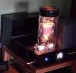
You can see lots of info on my direct-coupled A2 solution here:
https://www.diyaudio.com/community/threads/the-midlife-crisis-my-833c-amp-build.232484/
It's robust enough to routinely drive 200mA into the 833C grid which is running at 2.3kV. Ten years later still my main amps.
https://www.diyaudio.com/community/threads/the-midlife-crisis-my-833c-amp-build.232484/
It's robust enough to routinely drive 200mA into the 833C grid which is running at 2.3kV. Ten years later still my main amps.
Attachments
- Home
- Amplifiers
- Tubes / Valves
- A2 experiments