With both my turntable setups, it is possible to create a beautiful analog piece of music. Until a few years ago, I used to play with a set of Sowter MC step up transformers with excellent results. Still, I kept thinking if it could be even “better”; the bass remained a bit soft (compared to digital) and I had the feeling there was room for improvement, especially in terms of spatial image and ultrafine dynamics.
My thinking was to develop an active MC PRE PRE to solve this “problem”. Only a PRE PRE because I already had the Phonodude, and there was need to change that beauty! As usual, I didn’t want anything standard out of the box, like an uncreative low noise opamp circuit or similar. I wanted something totally out of the box addressing the needs and difficulties of the concept of a MC PRE PRE and make it as close as I could to a Tube amplifier to match the Phonodude Tube RIAA amplifier. For the simple reason I am till today convinced that the inherent linearity of tubes is the main reason they sound so great.
Below is the basic Story what I did - Pictures and circuit are below.
You can read also my blog of course
My considerations were:
A circuit idea and design goals were defined and I was ready to start developing:
Compared to common step-up transformers the bandwidth of the DD MC PRE PRE is pretty good. It starts at DC and the -3dB point is above the 200kHz mark of my AP test setup. The 200kHz mark is -1,5dB and only 0,5dB at 100kHz. Note, the low frequency cut-off will depend on the OUTPUT coupling capacitor you will use. On my DDDAC Website I have a nice table for this: LINK TO DDDAC SITE
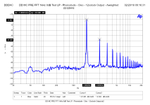
FFT measurement showing low distortion and low hum components (A-weighted). This is at a, compared to typical MC cartridges, high signal level of 10mV input (!). The d2 distortion is the only dominant one at roughly -60dB which equals 0,1% THD only. In practice the amplifier is distortion and hum “free”.
Final specifications:
*) Without Cartridge load which should be added depending on type cartridge
Conclusions
My thinking was to develop an active MC PRE PRE to solve this “problem”. Only a PRE PRE because I already had the Phonodude, and there was need to change that beauty! As usual, I didn’t want anything standard out of the box, like an uncreative low noise opamp circuit or similar. I wanted something totally out of the box addressing the needs and difficulties of the concept of a MC PRE PRE and make it as close as I could to a Tube amplifier to match the Phonodude Tube RIAA amplifier. For the simple reason I am till today convinced that the inherent linearity of tubes is the main reason they sound so great.
Below is the basic Story what I did - Pictures and circuit are below.
You can read also my blog of course
My considerations were:
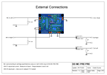
- There should be no coupling capacitor at the input because of the extremely fine input signals and the noise contribution the impedance of the capacitor will induce at that spot.
- Noise contribution had to be very low. Typical goal >70dB S/N ratio @ 0,5mV input signal.
- No opamps or anything needing NFB….
- A nice linear tube without negative feedback would be optimal, but they generate too much noise for these low signal levels.
- A J-FET at the input, mmmmhhh, yes, that’s not really new, but it works very much like a tube. Unfortunately, most designs have the problem of keeping the power supply interfering signals (noise and hum) at bay (PSRR has to be extremely high and that doesn’t really work well with the standard J-FET circuits you will find on the WEB). Also, the Power Supply Line is always in the signal path and normally only decoupled with a Elco capacitor (which again is in the signal path…)
A circuit idea and design goals were defined and I was ready to start developing:
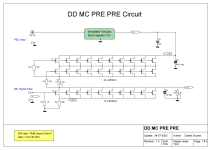
- To amplify the incoming signal, use a voltage controlled current source (VCCS), so that with a single resistor as load, you can do a linear I/V conversion directly to the common ground so Output Signal will be not seeing the PSU directly. (Just like in the DDDAC1794 I/V conversion…). The MC input is the voltage, controlling a current source (a J-FET), which will generate the output voltage by just running the current through a passive resistor. PSSR, DC-Bias and output voltage swing will be an issue, so we need more:
- Take another CONSTANT current source (CCS) that provides more current than the first one and let it drive the earlier mentioned stage. Some current will be “left over”. This differential “rest” current will flow to the output in a (Rload) load resistor. This means that the I/V stage works neatly in class A so there is DC-Bias at the output to allow for a voltage swing of the output signal around the DC-Point. A coupling capacitor is needed when your RIAA amplifier has none (Like the Phonodude). As a result, you kind of modulate the current through the resistor with the lower varying current. Result is amplified signal!
- The CCS must be as high impedance as possible, to have high PSRR. J-FETs do not do this, so it need to be a cascaded J-FET setup. This creates a CCS with very high output impedance in the Mohm range.
- Close off the design by feeding it with a very low-noise embedded Tent Shunt.
Compared to common step-up transformers the bandwidth of the DD MC PRE PRE is pretty good. It starts at DC and the -3dB point is above the 200kHz mark of my AP test setup. The 200kHz mark is -1,5dB and only 0,5dB at 100kHz. Note, the low frequency cut-off will depend on the OUTPUT coupling capacitor you will use. On my DDDAC Website I have a nice table for this: LINK TO DDDAC SITE
FFT measurement showing low distortion and low hum components (A-weighted). This is at a, compared to typical MC cartridges, high signal level of 10mV input (!). The d2 distortion is the only dominant one at roughly -60dB which equals 0,1% THD only. In practice the amplifier is distortion and hum “free”.
Final specifications:
| Gain | 5 to 25 (will be factory set on demand) |
| Input Impedance | 1k Ohm *) |
| Output Impedance | Aprox. 200 – 500 Ohm |
| Bandwidth (within 0 – 1,5dB) | 0 – 200kHz |
| Distortion at 10mV signal input | d2: 0,1% d3: 0,0025% |
| Output noise with inputs shorted (i.e. amplifier noise contribution) | ~20nV / SQRT(Hz) |
| Size | 58 x 73 mm |
| Power supply (DC) | 15V DC >100mA (per board) Audio Grade recommended |
Conclusions
- The measurements show that this is all VERY good for a discrete design. The DD PRE PRE has no need at all to hang around in the shadow from any other MC amplifier! On the contrary. It is difficult to get any better as the noise is almost at the level of the thermal noise of the cartridge’s coil DC resistance itself. Of course, you can’t get any better than thermal noise… Physical laws and all that.
- Sound wise, the DD MC PRE PRE amplifier benefits greatly from the lack of any negative feedback. It is just very linear, sounds open and natural as any well-designed tube amplifier, only d2 and almost no d3. You can easily hear that well; it sounds beautifully natural and never sharp or muddled. Compared to the Sowter transformers (I can still select the one or the other in my setup) it is so much tighter in bass and delivers a great spatial sound with low level detail. I am more than happy with this development. Even if it is mine to say…
- I’ve been playing music with this design for over a few years now to my complete satisfaction. The pre-pre sounds beautifully spacious, very finely detailed and with a tight bass. The self-noise is clearly below the vinyl noise itself.
- I call “Mission Completed” to develop something “completely different” and fantastic sounding.
- One last consideration; it is highly recommended to use a high-end coupling capacitor at the output to block the DC-Bias. It is worth it to get the maximum out of the amplifier. I use for example Mundorf Gold Silver Oil. But there are many other good brands of course. Your personal choice!
Attachments
-
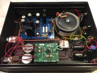 DD MC PRE 05.JPG487.2 KB · Views: 717
 -
 DD MC PRE 08.JPG242.2 KB · Views: 491
 -
 DD MC PRE 09.JPG291.4 KB · Views: 575
 -
 DD MC PRE 10.JPG514.5 KB · Views: 633
 -
 DD MC PRE FFT 1kHz 0dB Test LP - Phonodude - Cleo - 12oclock Output - Aweighted 22-22kHz.png31.8 KB · Views: 916
 -
 DD MC PRE PRE Circuit 12b_1.png60.3 KB · Views: 933
 -
 DD MC PRE PRE Circuit 12b_2.png108.9 KB · Views: 876
 -
 DD MC PRE THD vs Input Voltage 10mV.png30.8 KB · Views: 706
 -
 MC Pre with BC861 - 1 FET Only - basic BIAS test V1RT20-noise only.GIF10.8 KB · Views: 737
It should be reversed phase at the input cable on MC head, because this (like any other same topology single ended) MC stage shifts phase for 180deg.
Phase didn't show at the measurements.
.
Also reducing a gain with the R (pot) load direct at the output of the device will give compression/limier effect.
Even with very low output impedance of paralleled JFETs (les than Rdson /10) ther load is too low.
The amount of compression can be determined with measurements with large load 470K or without load at all.
And present 2Kload. The difference in db will show amount of effect...
.
There is some local feedback since the Rsource of amplifinig JFET is not briged with some C. Probably because arady more than sufficient gain. And for these low values of Rsource Csource should be very large values. more than 2200uF...
Thanks for feedback and observations Zoran. The phase topic has little to do with the MC pre pre as such. If you want phase correct signal reproduction, I would always do it at speaker level. easiest to do. Besides, you never know if the recording from the studio was phase correct? anyway, I did not want to open that discussion. But yes, you are correct, the PRE PRE has 180 degrees phase shift.
There is no "compression or limiter effect". This is a thing from the PA world, where gain is reduced at high levels (or increased at low levels) to keep sound pressure on. If the signal is lower due to load of the stage, in general (true for every stage) there is lower gain, for all levels of signal and all frequencies. The trimmer is to adjust exact gain for both channels, which is normally difficult, and I wanted to tap signal from same ground as MC cartridge and avoid decoupling of power line, as described in the post. It was part of the design goals as described on the post. I believe that a few hundred ohm output impedance is pretty good and low enough as most RIAA amps has 47k input impedance (not 2k).
I deliberately wanted to avoid any large electrolyte capacitors in decoupling of signal. the 20 Ohm is a good optimum between noise contribution and bias current needed. so it is fine for me. The local feedback if applies is very low. Without 20 Ohm, max gain is only 45x
Hi DDdac, I mismatch a thing that Your construction is not a classic CCS loaded circuit. The output point is taken from the "upper" side of P and Source summ point of CCS. (in classic mode the output point is from "lower side of pot and Drain of activre amplifiacation jfet-s...
I am sorry that i made that mistake.
This is a sort of folded cascode topology as I may say.
I replaced P2 with P-JFET CCS J174 same current as 2K P2, Drain on the GND orientation...
(I had PSpice model, but better to be same package as other JFETs...)
The cureenf flow trough that "shunt" can be adjusted via Rs of the cascode P-JFET CSS
And results was about -3.5db in FFT base line. Maybe this is from importance?
Also I think that introducing the negative power supply line You can get zero off-set and avoid output coupling cap?
I will sketch the sch.
.
I was working eith BF861C only. (Because BF862 in not in production 🙁 )
I choose C version because from the datasheet it is more linear than other versions.
Did You try to put C version in input 10X line insted of B version as in SCH?
Hi Zoran,
thanks for sharing thoughts and ideas. Interesting thought to change P2 for another CCS. One open question for me is how you define the gain in that case?
I used the B for reason of lower transconductance, so I would have the "extra current" at roughly the same bias point for the C version. I remember when calculating using both C-versions just did not gave me a good feeling of operation point.
The BF861B is available at Octopart in the thousands.... I also have a full reel lying around 😉
Oh yes, I indeed thought about an adjustable negative rail with a servo to get to a few mV DC at the output. It is still on my short list for the far future ;-) But I still have trouble with the idea, that the negative rail would be in the output circuit and hence contribute to the noise and power supply influence .... So, I thought it better to start with a de-coupling capacitor.
Hi DDac
The gain coud be defined via P1 100ohm pot. But it is sensitive somehow?
I used a value of bit smaller than 33ohms for P1.
The replacement circuit for P2 (of 2K, with around 5mA Io) could be done with P-JFET one or cascoded 2 jFETs
And also thhere is a option to change the current changing tha value of Rs in the circuit.
From the PSpice model for J174 cascoded for 5mA cca. Rs is around 980 ohms.
But that it could be easily first checked in praxis with simple power supply around 10-11V thest setup?
The PSpice models I used for JFWTs are from philips and I got the almost same results as im Your sch verified in practice.
Take a look at Groner's CCS in his ultra-low noise amplifier -- in Linear Audio. You might want to do a "bake-off" comparing the shunt regulator with Groner's design, comparing noise, PSRR and Z-out. It is very, very low noise.
WRT the paralleled JFETs -- some have found it necessary to decouple the gates with small inductor.
WRT the paralleled JFETs -- some have found it necessary to decouple the gates with small inductor.
@ Jackinnj Thanks for the tipp. I see it is Linear 3 book. Will have a look later (need to dig it up somewhere). What would be the benefit of decoupling the gates?
@ Zoran my somewhat reduced library in TINA Spice has no J174 PFET. So cannot simulate. Still not sure what the benefit would be not using a fixed resistance to set the gain? Maybe you can elaborate what your thoughts were on suggesting this?
@ Zoran my somewhat reduced library in TINA Spice has no J174 PFET. So cannot simulate. Still not sure what the benefit would be not using a fixed resistance to set the gain? Maybe you can elaborate what your thoughts were on suggesting this?
Hi DDac I emulate again with more precise settings and there are no obvious benefits... 🙁
You can use some P-JFET more than 6mA of Id?
I think I can extract PSpice model for J174 and post.
.


You can use some P-JFET more than 6mA of Id?
I think I can extract PSpice model for J174 and post.
.
@ Zoran my yes, would like the spice model and see if I can import in TINA
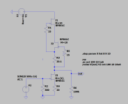
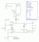
@ Jackinnj Before I start desoldering on my boards, what is it exactly you want to find out? The circuit is not what it is in reality. the bottom FET is the B version and there is no real output load ? for gain = ~20 you need ~700 Ohm.
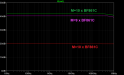
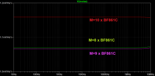
Not sure on the function where you can enter the qty of the part. You could check if the DC Bias is changing when you go from 10 to 9 for example. It has to of course.
Edit: by the way, if I reduce the number of FETS by half in my simulation I get as expected 3dB more noise
Last edited:
I am using BF861C vesion as amplidication jfet-s
I think that is more linear than A and B
.
As @ Jackinnj put in the sch...
.
I think that is more linear than A and B
.
As @ Jackinnj put in the sch...
.
Please do yourself a favor and replace this with a proper capacitor. You pre-pre deserves it!Mundorf Gold Silver Oil
Did you consider using a much better JFET than BF861?
https://www.ti.com/lit/ds/symlink/jfe150.pdf?ts=1690643552689&ref_url=https%3A%2F%2Fwww.ti.com%2Fproduct%2FJFE150
With only 10x JFE150 noise would be lower than with 60x BF861 and CCS would need to deliver much lower current, having better PSRR in return with the same design.
https://www.ti.com/lit/ds/symlink/jfe150.pdf?ts=1690643552689&ref_url=https%3A%2F%2Fwww.ti.com%2Fproduct%2FJFE150
With only 10x JFE150 noise would be lower than with 60x BF861 and CCS would need to deliver much lower current, having better PSRR in return with the same design.
Have you considered alternate lower noise JFETs like the new JFE150 ? Have you compared to ZTX851/951 based design, noise-wise, which is the lowest voltage noise device I know of.Edit: by the way, if I reduce the number of FETS by half in my simulation I get as expected 3dB more noise
The Mundorf S&G are a serious red flag for me too. They can overwhelm the presentation like an overly strong spice. Perhaps good for tweeter crossovers, but little else.
Once you build this using proper parts the overall budget becomes comparable to a proper transformer, perhaps from Tribute, or even one of the better Lundahls with Cardas wire. Still, a very different presentation, so still a worthwhile project.
Once you build this using proper parts the overall budget becomes comparable to a proper transformer, perhaps from Tribute, or even one of the better Lundahls with Cardas wire. Still, a very different presentation, so still a worthwhile project.
- Home
- Source & Line
- Analogue Source
- A ultra low noise Moving Coil Pre Preamplifier with 60x BF861 and Tentlabs embedded Regulator
