You have two options:
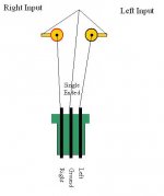
1) You can split your grounds before the board and run Signal and GND to each side of the board (for balanced: IN+ and GND to one side, and IN- and GND to the other, one channel per board; for SE, R+ and GND to one side and L+ and GND to the other side), or
2) You can run a single ground to one side and add a jumper at J2, which will supply GND to the other side.
Which ever is easier for your wiring setup. [/B][/QUOTE]
Huh?
Ok let me show you the depth of my ignorance. Besides I'm a visual learner. Is the picture below right?
Attachments
Ooops I just realized I posted in the wrong thread. This should be in the DARWIN thread. Sorrrry
JT 1.1 PICs
Okay, I just sent out new PICs to all who bought Joshua Trees with the v1.1 code.
US: You should have then on or before Wednesday.
non-US (except Canada): You shoudl have then in 1.5 - 2 weeks depending in customs.
Canada: You should have them by Q3 2009.
Okay, I just sent out new PICs to all who bought Joshua Trees with the v1.1 code.
US: You should have then on or before Wednesday.
non-US (except Canada): You shoudl have then in 1.5 - 2 weeks depending in customs.
Canada: You should have them by Q3 2009.
Member
Joined 2002
Help with jumpers, etc.
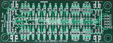
Can someone help me understand the function of the jumpers on the Joshua Tree relay board.
I think J2 is used for balanced configuration, which requires 2 relay boards, and it appears J1/J3 share the input across both sides of the relay board. Under what circumstances would you use J1/J3?
Plus, is there any reason the diodes cannot be mounted above the relays rather than on the bottom side of the PCB?
Thanks.
Attachments
Re: Help with jumpers, etc.
Normally you don't need to use any jumpers. J2 is there in case you have a balanced configuration or want to simply run three wires (L+R+GND) to the PCB insstead of 4.
The other two jumpers turn the PCB into a single channel at half the impedance. It is normally not used I just provided it as an option.
Sure you can easily put the diodes above the relays if you like. It should work just fine.
Cheers!
Russ
orthoefer said:Can someone help me understand the function of the jumpers on the Joshua Tree relay board.
I think J2 is used for balanced configuration, which requires 2 relay boards, and it appears J1/J3 share the input across both sides of the relay board. Under what circumstances would you use J1/J3?
Plus, is there any reason the diodes cannot be mounted above the relays rather than on the bottom side of the PCB?
Thanks.
Normally you don't need to use any jumpers. J2 is there in case you have a balanced configuration or want to simply run three wires (L+R+GND) to the PCB insstead of 4.
The other two jumpers turn the PCB into a single channel at half the impedance. It is normally not used I just provided it as an option.
Sure you can easily put the diodes above the relays if you like. It should work just fine.
Cheers!
Russ
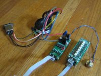
I just finished my Joshua Tree attenuator and discovered first hand something that I think is already known about this kit. Using my 6V (30VA) transformer, I get super flakey activity with two relay boards chained together. In this configuraion, the relays chatter at upper volume ranges, then fizzle out and reset. Is this the "motor boat" that others decribed? I am pretty sure everything is soldered and oriented correctly because the relays behave with just one board and the 6V supply.
Fortunately my transformer is center tapped 6V-0-6V, so I can get 12V out of it. Changing to 12V makes everything stable with 2 realy boards. No more random clicking at upper volume ranges. However, I am concerned about the amount of heat coming from the heatsink on the regulator with 12VAC input.
Thoughts? I cannot imagine that the 30VA transformer isn't providing enough current at 6V.
Plus, where can I find the most up to date schematic?
Attachments
The regulation just is not very good at 6V. Thats why you get the flaky behaviour.
Do you have the updated firmware?
The HS will get warm when running as it is delivering a pretty good chunk of current to the relays. It shoud be just fine if you use the supplied heatsink.
I am running mine with 12VAC. It does run pretty warm, but nothing to fret about.
Cheers!
Russ
Do you have the updated firmware?
The HS will get warm when running as it is delivering a pretty good chunk of current to the relays. It shoud be just fine if you use the supplied heatsink.
I am running mine with 12VAC. It does run pretty warm, but nothing to fret about.
Cheers!
Russ
Russ, thanks for the super fast response. I am pretty sure I have the updated firmware 1.1--right? On the JT, is it possible to measure variable resistance from input to output like with a potentiometer? (Forgive my ignorance, I am still learning the basics). Thanks again.
orthoefer said:Russ, thanks for the super fast response. I am pretty sure I have the updated firmware 1.1--right? On the JT, is it possible to measure variable resistance from input to output like with a potentiometer? (Forgive my ignorance, I am still learning the basics). Thanks again.
OK great, yes thats the latest firmware.
As for resistance, it does not really work like a pot. You can measure the input and output impedance, and you can measure voltage in vs voltage out. Just attach a 1.5V(battery) supply to in and gnd and measure between out and gnd.
Cheers!
Russ
I just build the first JT board.
To test it, I measured the output impedance. At some point (let say 2/3 of the pot) the impedance begin to rise to about 2k9. When turning the pot almost to its max is drops to zero and the last few 'clicks' of the pot it is back to 750E.
Shouldn't the output resistance be constant at 750E?
Gr, Bastiaan
Measure output impedance by connecting In and GND and then measure between in and out.
If you still get strange results (it should be close to 750R entire range of attenuation) then I would suspect a resistor is in the wrong spot.

Cheers!
Russ
If you still get strange results (it should be close to 750R entire range of attenuation) then I would suspect a resistor is in the wrong spot.
Cheers!
Russ
Russ White said:Yes it should be, how did you measure?
I measured it between the GND and the OUT using a multimeter.
--
I just read your second post, I didn't connected the IN to the GND. That did the trick. It is now 750R over the full range.... 😀
I'll try to connect a battery tomorrow. Just to be sure it is working correctly.
Thanks
Blimp said:
I measured it between the GND and the OUT using a multimeter.
--
I just read your second post, I didn't connected the IN to the GND. That did the trick. It is now 750R over the full range.... 😀
I'll try to connect a battery tomorrow. Just to be sure it is working correctly.
Thanks
Ahhh very good. If you are getting constant output impedance you can be assured it is working correctly.
Cheers!
Russ
An observation
Russ, I connected a 1.5V battery to the input of the JT and measured DC voltage at the output. Over most of the range of the controller's potentiometer, I get what I expect--a gradual increase in voltage to 1.5V but then with increasing clockwise rotation, the output goes to 0V. The last 12 clicks or so from the relay board are 0V. Is this normal operation? See my plot below and notice the drop off to 0V on the right. This is the same finding regardless of channel and regardless of relay board (I have two operating from the same controller).
Russ, I connected a 1.5V battery to the input of the JT and measured DC voltage at the output. Over most of the range of the controller's potentiometer, I get what I expect--a gradual increase in voltage to 1.5V but then with increasing clockwise rotation, the output goes to 0V. The last 12 clicks or so from the relay board are 0V. Is this normal operation? See my plot below and notice the drop off to 0V on the right. This is the same finding regardless of channel and regardless of relay board (I have two operating from the same controller).
An externally hosted image should be here but it was not working when we last tested it.
You have found a "feature" (well ok a bug) in the new firmware. I just tested this myself and in fact you are right. It appears I have some mathmatical error in the firmware that I never discovered in my testing since I did not actually check (slaps self hard on forehead) output voltage, and I rarely turn my amp up that loud. 🙂
Let me look and see if there is a simple fix.
Let me look and see if there is a simple fix.
There is no risk in operating it this way it should work fine, just don't turn the knob too high, or it will get quiet. 🙂 I am very very sorry, I will work this out.
Russ,
Thanks for reviewing my JT performance plot. I updated the plot in the earlier message to reflect observed output vs. theoretical and normalized the voltage. A refresh of the browser window should bring up the new graphic.
If there is a firmware update, I will gladly cover all shipping and the cost of a new PIC.
In the mean time, this project is really great. Kudos for your design and engineering vision. The JT is fantastic.
Hi Russ,
your software seems just right.
Someone turning up the stereo this loud deserves (needs?) to have the output muted to protect their speakers and their ears. The neighbours like your present software as well.
If one was testing the attenuation into a dummy load then the muting action does not matter. It is a clear indicator that one has past the maximum output.
It's just your embarassment at trying to describe this as the preferred arrangement. A good advertising copyist could invent even more attractive sounding advantages to this bug.
- Status
- Not open for further replies.
- Home
- Design & Build
- Parts
- A twisted tale about a logarithmic relay attenuator