Hey guys disregard the first layout I posted, it actually has a couple problems, and I am working on a much better one.
Here is the plan. I will be posting PDFs for a single side version(actually a few versions) and Brian and I will likely produce kits for a more optimized double side version(s).
Cheers!
Russ
Here is the plan. I will be posting PDFs for a single side version(actually a few versions) and Brian and I will likely produce kits for a more optimized double side version(s).
Cheers!
Russ
promitheus said:
A mute Relay would be helpful to make a time delay on turn on etc.
A mute relay would be a nice addition if Russ decides to it, an easy addition if space allows. The board looks quite crowded as is so let’s hear if this is possible.
apassgear said:
A mute relay would be a nice addition if Russ decides to it, an easy addition if space allows. The board looks quite crowded as is so let’s hear if this is possible.
A mute relay (optional when stuffing the PCB) will be on the new PCB. Stay tuned. 🙂
Russ,
I was looking at the pic board again. Naturally, I am IMpatiently awaiting the kit. Or at least the boards.
Anyway, I have a few requests that would make your boards more flexible for DIY use:
1. Can you wire all 18 outs to resistor/FET output Pads?
2. Can you add an ICSP header?
3. Can you make the unused portion of the board into vector board? Or better yet, Proto space with power & ground lines, and trace connected pads for easy circuit addtion?
4. How about a Crystal mounting spot?
Actually, I think making the spareboard into proto space would solve all issues. I could easily add anything I want! The possibilities are endless!
FYI, I have never done any PIC or PCB stuff, so my comments may be complete newbie drivel. Feel free to say "Objections Noted" and ignore me if I'm full of BS!
herm
I just thought of another advantage of this set up. Because it uses a pot instead of an encoder, it can be retrofitted into almost any piece of gear with a pot. Just put it in line.....minimally invasive. Pretty cool!😀

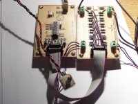
Second prototype
Note IDC connectors and only six jumpers. 🙂
There are pads for all the available pins on the PIC and one each for GND and +5V. 🙂
It sounds great, with clean/smooth volume transitions.
The two PCbs are designed to be stacked, but I don't have the correct standoffs right now (on order). But even side by side they are smaller than a standard CD case.
Cheers!
Russ
Attachments

I would like to try this with a 48-24-12-6-3-1.5-0.75 sequence giving 96dB range, 64dB is not really enough range.
7 x 5V telecom relays would draw a lot of current, typically these each have a coil resistance of about 100R. 24V relays are over 2k5, so in my old Cambridge C70 preamp I think that 24V relays would be better as the raw dc is about +/- 25V. The microcontroller consumption is negligible.
7 x 5V telecom relays would draw a lot of current, typically these each have a coil resistance of about 100R. 24V relays are over 2k5, so in my old Cambridge C70 preamp I think that 24V relays would be better as the raw dc is about +/- 25V. The microcontroller consumption is negligible.
The omron Relays use very little currect.
Russ White: if you use those flat cable connectors you can easily stack the boards on top of each other and make one cable for all.
Those connectors should be universal so anybody can there own cables.
Everything looks great.
Russ White: if you use those flat cable connectors you can easily stack the boards on top of each other and make one cable for all.
Those connectors should be universal so anybody can there own cables.
Everything looks great.
The prototype uses Omron G6K 5V relays, which draw on the order of 20-30mA each. Not much at all. These are DPDT 8-pin relays.
promitheus said:Russ White: if you use those flat cable connectors you can easily stack the boards on top of each other and make one cable for all.
Yep, that was the idea. 😀
Thanks!
davidsrsb said:I would like to try this with a 48-24-12-6-3-1.5-0.75 sequence giving 96dB range, 64dB is not really enough range.
Easy enough. I will post some possible values for you later.
The G6K draw tiny amunts of current. With all rleays on the entire circuit draws less than 250ma.
Cheers!
Russ
OK folks,
Here is a basic PCB layout as promised. It does 128 steps from -63.5 to 0 db attenuation.
TLA_1_0.zip
The controller is the basic controller, with just the potentiometer to ADC volume control, but I added pads for all unused PIC IO pins, and one each for GND and +5V.
You will need:
Double everything for a balanced pair.
Below is the resistor list for 1.5K output impedance which results in an input impedance range from 3698 to 61296 ohms. If you want to you could flatten this out a bit by placing a 10K resistor between signal IN and GND.
R1 1580
R2 26700
R4 182
R6 13700
R7 392
R9 7320
R10 887
R12 4020
R12S 88.7
R13 2260
R15 2430
R15S 53.6
R16 7870
R16S 82.5
R18 1780
R19 57600
R19S 665
R21 1540
You will notice that in some places there is a R# and R#S resistor listed. That is because to get the optimal value two resistors in series should be used. The PCB is designed to accommodate those resistors. If you wish you can omit the low value resistor and simple jumper the omitted resistor, but you will lose some linearity.
This should be sufficient for those of you who have just want to get a simple attenuator going. I am currently starting an integrated “My Ref” Revision C amplifier project using this attenuator. And I will likely use that same values for my Twisted XBOSOZ. I will post some other versions later (with mute and such) but I would not hesitate to build this version, as -63.5 db is almost as good as full mute. 🙂
Have a lot of fun, and feel free to ask questions.
The HEX file for the PIC is included in the zip.
The programmer is based on the RCD programmer by FENG3 which you can read more about here:
http://feng3.cool.ne.jp/en/rcd.html
I made space for the TEXTOOL type 20 pin ZIF socket on the PCB which works great for me.
And I use the PICPgm software you can find here:
http://www.members.aon.at/electronics/pic/picpgm/index.html
When using PICPgm the RCD will work as a JDM programmer, that is what you want.
I am using the HI-TIDE IDE and PICC Lite (free) to develop my firmware.
http://www.htsoft.com/products/PICClite.php
Cheers!
Russ
Here is a basic PCB layout as promised. It does 128 steps from -63.5 to 0 db attenuation.
TLA_1_0.zip
The controller is the basic controller, with just the potentiometer to ADC volume control, but I added pads for all unused PIC IO pins, and one each for GND and +5V.
You will need:
7 G6K-2P relays
7 BC546A or equivalent, many different NPN transistors will work fine
20 pin Dip socket (in case you want to reprogram your PIC)
PIC16F685,16F687,16F689,or 16F690 (I used the PIC16F690)
A PIC programmer (I have included in the ZIP PDFs for a reasonably good one).
7 1K resistors for the IO pins to the transistors
4 screw terminals – 2 position, 5mm pitch
2 2x7 pin headers. I used shrouded IDC type.
2 2x7 IDC connectors.
A short length of 14 conductor IDC ribbon cable
Some good hookup wire for the jumpers between the pads on the attenuator PCB.
Double everything for a balanced pair.
Below is the resistor list for 1.5K output impedance which results in an input impedance range from 3698 to 61296 ohms. If you want to you could flatten this out a bit by placing a 10K resistor between signal IN and GND.
R1 1580
R2 26700
R4 182
R6 13700
R7 392
R9 7320
R10 887
R12 4020
R12S 88.7
R13 2260
R15 2430
R15S 53.6
R16 7870
R16S 82.5
R18 1780
R19 57600
R19S 665
R21 1540
You will notice that in some places there is a R# and R#S resistor listed. That is because to get the optimal value two resistors in series should be used. The PCB is designed to accommodate those resistors. If you wish you can omit the low value resistor and simple jumper the omitted resistor, but you will lose some linearity.
This should be sufficient for those of you who have just want to get a simple attenuator going. I am currently starting an integrated “My Ref” Revision C amplifier project using this attenuator. And I will likely use that same values for my Twisted XBOSOZ. I will post some other versions later (with mute and such) but I would not hesitate to build this version, as -63.5 db is almost as good as full mute. 🙂
Have a lot of fun, and feel free to ask questions.
The HEX file for the PIC is included in the zip.
The programmer is based on the RCD programmer by FENG3 which you can read more about here:
http://feng3.cool.ne.jp/en/rcd.html
I made space for the TEXTOOL type 20 pin ZIF socket on the PCB which works great for me.
And I use the PICPgm software you can find here:
http://www.members.aon.at/electronics/pic/picpgm/index.html
When using PICPgm the RCD will work as a JDM programmer, that is what you want.
I am using the HI-TIDE IDE and PICC Lite (free) to develop my firmware.
http://www.htsoft.com/products/PICClite.php
Cheers!
Russ
Here are some resistor values for 1.5K output impedance and .75db steps from -95.25db to 0db
Rin:0 Rout:1500 -db:-0.75
R1: 1635.28 R2: 18132.57 R3: 0
E96 R1: 1650 R2: 18200 R3: 0
E96S R1: 1650 & R1S: 0 R2: 18200 & R2S: 95.3 R3: 0 & R3S: 0
E96S Totals R1: 1650 R2: 18295.3 R3: 0
-------------------------------------------------------------------
Rin:1500 Rout:1500 -db:-1.5
R4: 282.75 R5: 0 R6: 9457.47
E96 R4: 280 R5: 0 R6: 9310
E96S R4: 280 & R4S: 0 R5: 0 & R5S: 0 R6: 9310 & R6S: 54.9
E96S Totals R4: 280 R5: 0 R6: 9364.9
-------------------------------------------------------------------
Rin:1500 Rout:1500 -db:-3.0
R7: 618.81 R8: 0 R9: 5136.03
E96 R7: 619 R8: 0 R9: 5110
E96S R7: 619 & R7S: 0 R8: 0 & R8S: 0 R9: 5110 & R9S: 27.4
E96S Totals R7: 619 R8: 0 R9: 5137.4
-------------------------------------------------------------------
Rin:1500 Rout:1500 -db:-6.0
R10: 1492.89 R11: 0 R12: 3007.14
E96 R10: 1500 R11: 0 R12: 3010
E96S R10: 1500 & R10S: 0 R11: 0 & R11S: 0 R12: 3010 & R12S: 11.5
E96S Totals R10: 1500 R11: 0 R12: 3021.5
-------------------------------------------------------------------
Rin:1500 Rout:1500 -db:-12.0
R13: 4471.61 R14: 0 R15: 2003.17
E96 R13: 4420 R14: 0 R15: 2000
E96S R13: 4420 & R13S: 44.2 R14: 0 & R14S: 0 R15: 2000 & R15S: 0
E96S Totals R13: 4464.2 R14: 0 R15: 2000
-------------------------------------------------------------------
Rin:1500 Rout:1500 -db:-24.0
R16: 22273.4 R17: 0 R18: 1601.02
E96 R16: 22600 R17: 0 R18: 1620
E96S R16: 22100 & R16S: 442 R17: 0 & R17S: 0 R18: 1620 & R18S: 0
E96S Totals R16: 22542 R17: 0 R18: 1620
-------------------------------------------------------------------
Rin:1500 Rout:1500 -db:-48.0
R19: 375283.03 R20: 0 R21: 1506
E96 R19: 374000 R20: 0 R21: 1500
E96S R19: 365000 & R19S: 8870 R20: 0 & R20S: 0 R21: 1500 & R21S: 0
E96S Totals R19: 373870 R20: 0 R21: 1500
-------------------------------------------------------------------
Cheers!
Russ
Hi,
I tried your resistor calculator to produce a 200r output impedance with a 60source and 200out for the first stage and then 200source 200out for the remaining 4 relays. -38.75db in 1.25db steps.
Unfortunately the input impedance drops very low whenever a relay pulls in to start attenuating.
Is there a trick connection that maintains a higher input impedance and still maintain the low output impedance?
So, uncle Russ, will you be selling pics loose then?
Allthough I'd probably wait for the integrated Rev C (Rev D?).
As my current Rev C's weakpoint is the pot I'm using... its a massive step up financialy to get a good pot. In fact a good pot costs as much as the rest of the components combined.
Allthough I'd probably wait for the integrated Rev C (Rev D?).
As my current Rev C's weakpoint is the pot I'm using... its a massive step up financialy to get a good pot. In fact a good pot costs as much as the rest of the components combined.
- Status
- Not open for further replies.
- Home
- Design & Build
- Parts
- A twisted tale about a logarithmic relay attenuator