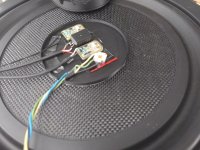
Yes. It was quite a tedious job. The TangBand W5-1138SMF basket and cone are close together, and the magnet is relatively big. No space to put the connectors. No space for the coax wires and no space for anything. 🙄Ah now I see how this works. I was wondering how you got the signal out. You basically create a new set of tinsel leads and terminals through the cone and on the basket.
Everyone is telling me, that tiny 5" driver and MFB cannot go together.
As you likely know, this company markets a small 2 way speaker with MFB on a 5" Scan-Speak midwoofer for €1500 a pair. Don't know how successful it is commercially but they are around. A slightly larger 3 way offering a bit more performance for a bit more money looks reasonable to me.
Voltage amplifier will be used. At least for start. They are available everywhere. If there is something working I may try with current amp.
Likely wise. A working first prototype and a well optimised developed speaker (e.g. Philips) are different things.
I am not good with speakers and was asking the same question myself about the added mass. At that time I used an online calculator.
The sensor is not 63 grams (7.5 grams actually). An extreme case was checked. Sadly the site is not available anymore. (mh-audio).
Added mass often isn't much of an issue for woofers/subs but it will lower the sensitivity a bit and require more power to restore the SPL.
Against rocking ... the sensor is positioned at the top of the voice coli. At the cylinder axis. Don't know if it is enough.
The longer the stroke, the less is required to deviate from moving in and out in a straight line. My comment was prompted by Boden's comment that Philips stiffened their suspension. However the 70s was in the days of floppy suspensions for acoustic suspension cabinets. A stiffer modern suspension may not have an issue. @Boden do you have a link to help clarify?

Andy, keep in mind that because of the large bandwith, the woofer is making large excursions in a small enclosure, leading to high pressures on cone and surround.
The Philips 86xx and 76xx series were never true acoustic suspension woofers like e.g. the Braun 20cm units (L/LB500 system) or AR 3/3a/4 etc. woofers, but had nonetheless rather soft rubber surrounds.
The Philips 86xx and 76xx series were never true acoustic suspension woofers like e.g. the Braun 20cm units (L/LB500 system) or AR 3/3a/4 etc. woofers, but had nonetheless rather soft rubber surrounds.
A bit of history: Some years ago (2011 to be precise) a friend of mine bought a box of Philips AD7066/MFB. Maybe 30 pieces or more. New old stock.
So - we had to use them. The first trials with MFB were more than annoying and unfortunately the projects started with the speakers were not finished except one. A small bookshelf with Visaton B80. After that I gave up playing with MFB until the present days. Since AD7066/MFB cannot be found new I had to mount an accelerometer to another driver before continuing making the actual speaker.
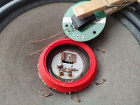
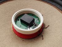
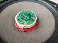
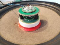
@Boden. You mentioned different accelerometers. Let me show some old pictures. This way I tested Philips piezo vs ACH-01 vs the Murata diy accelerometers. 3d printed spacers and sensors one ovet the other. Ugly, but it was ok for tests.
So - we had to use them. The first trials with MFB were more than annoying and unfortunately the projects started with the speakers were not finished except one. A small bookshelf with Visaton B80. After that I gave up playing with MFB until the present days. Since AD7066/MFB cannot be found new I had to mount an accelerometer to another driver before continuing making the actual speaker.
@Boden. You mentioned different accelerometers. Let me show some old pictures. This way I tested Philips piezo vs ACH-01 vs the Murata diy accelerometers. 3d printed spacers and sensors one ovet the other. Ugly, but it was ok for tests.
Attachments
Last edited:
Hats off! No doubt you have found out the hard way how important sensor mounting (place+manner) is in order to achieve proper ULF woofer tracking.
I wish I was a mechanical guru, but i am not. : / Sensor mounting is of ultimate importance, and I am still struggling to find a good compromise.
The PCBs are ordered to JLCPCB. Some of the 3D parts also.
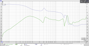
Take a look at the Senther 540C. The blue graph. Impressive low frequency extension.

The PCBs are ordered to JLCPCB. Some of the 3D parts also.
Take a look at the Senther 540C. The blue graph. Impressive low frequency extension.
A closed box should show a monotonic straight 12dB/octave line at ULF, not a rising response below 10Hz.
That being said, measuring accurately below some 7-8 Hz is very difficult.
It is possible the box is not airtight, the woofer cone is wobbling, the sensor is not optimally mounted, the gear is not accurate or outside rumble impacts the measurement. Can you make a LF Nearfield measurement of the woofer itself and overlay the traces? At least it is then clear what the woofer itself does at ULF.
In my appartment is near impossible to get useful measurements below 8 Hz.
Try the wayback machine:Sadly the site is not available anymore.
https://web.archive.org/web/20240224223352/http://mh-audio.nl/
Some luck always helps : ). I found the test jig almost intact and measured again from 1Hz. I put the scope to DC. Don't remember was it AC or DC the previous time.
Red graph is the Senther. At 1Hz signal amplitude is ~ 2mV. From the DIY Murata sensor the signal is barely visible (maybe 200-300uV). Almost buried into the noise floor.
The phase is 180 degrees reversed for the two measurements but seems equal. IMO the frequency response of the DIY accelerometer is comparable to the Senther.

The measurement is not in a closed box. It is a 10" shallow Dayton LS10-44 on the bench, that is used as a vibration table.
Red graph is the Senther. At 1Hz signal amplitude is ~ 2mV. From the DIY Murata sensor the signal is barely visible (maybe 200-300uV). Almost buried into the noise floor.
The phase is 180 degrees reversed for the two measurements but seems equal. IMO the frequency response of the DIY accelerometer is comparable to the Senther.
The measurement is not in a closed box. It is a 10" shallow Dayton LS10-44 on the bench, that is used as a vibration table.
https://web.archive.org/web/20230603020044/http://www.mh-audio.nl/calculators/tunewoofer.htmlTry the wayback machine:
https://web.archive.org/web/20240224223352/http://mh-audio.nl/
It works! Thank you!
I am in a very noisy environment, but at least something can be seen. Green graphs are the mic measurements.Can you make a LF Nearfield measurement of the woofer itself and overlay the traces? At least it is then clear what the woofer itself does at ULF.
In my appartment is near impossible to get useful measurements below 8 Hz.
Orange is the Senter, blue is the diy accelerometer.
Dayton LS10-44 was measured by wankel4486 a few years back in this post..
This is the direct link to his measurement.
https://www.diyaudio.com/community/attachments/dayton-ls10-44-mfb-pxe_out-vspk-png.1171609/
Attachments
- Home
- Loudspeakers
- Multi-Way
- A tiny three way with a twist