I wasn't sure where to put this question on the site, but since it could be used as an output stage I thought Amplifiers and Solid State would suit it.
Has anyone used, or looked at a Darlington as a main part of a CFP output stage? So that would be three transistors; one cascading into the other and a CFP wrapped around it?
I am a very big fan of CFPs in general and have used them in high power regulators. They seem to lighten up the clumsiness of big power transistors and the local feedback really appeals to me.
The two applications I would be looking at are as plain output sections in either and amplifier or a voltage regulator - though probably the regulator first. Though I know that Douglas Self abhors packaged Darlingtons (and I do take his point) but there is a huge temptation to use one of those high current packages where you have a Darlington with two power devices in the same box (preferably not TO-3). Does anyone have any idea what might be a suitable choice?
The other possibility was to CFP a CFP, meaning that you take a compound pair, treat it as an NPN, and then wrap another transistor around it, but put it on the other side of 0V. This would get you extra local feedback and get rid of PN junctions between your rails and the signal.
I'm sure any of these could be made to work but the question is whether you are going to run into a wall of practicality and oscillation.
Also, if anyone knows of a package with two plain devices in it, in parallel, could they please let me know. I think I have looked and looked but I just can't find them.
One final thing is that I can't seem to get any definitive information on output impedance differences between various output stages. Ideally I am after a flat impedance which can be modeled as a pure R+L and which doesn't change much under load. The Hfes of the Darlingtons I have looked at seem very humped and tend to only get going around 5A, which is not what we are used to in some of the nicer power transistors today. Not affecting the load resistance of the VAS is something I regard as critical and it would tempt me to use a MOSFET as the pickup driver, but that perhaps rather kills the idea I have in mind.
Many thanks, Christian
Last edited:
Sanken have a considerable range of high quality power darlingtons for audio and other applications. There are only two complementary pairs now that feature thermal sense diodes as well ( STD01N/P or STD03N/P) but general purpose and audio power types are widely used too.
Allegro MicroSystems - Sanken Audio Transistors
Allegro MicroSystems - Sanken Audio Transistors
Three stages/devices is the point where stability becomes difficult. Each one only has to do 60degrees phase shift and then you have oscillation. You would need to ensure that there is a dominant pole, but then you will lose gain at HF. My guess is the fact that this arrangement is rarely used is because it is difficult to keep stable.
What DF96 says. You can get it to work, but stability can be iffy. The main benefit of CFP is that there can be a lot of loop gain, but a very short low phase shift path, so it works really well. But add another junction with phase shift and that goes away.
Thanks for that link Ian.
DF96, but we happily use 3 stages as emitter followers where each of the shifts sum. I'm not sure exactly what happens with the poles in a CFP configuration - whether some sort of mean is reached - but I imagine that the slowness of the power transistor gets corrected for to some extent and then eventually you get a 2nd order rolloff. So in some ways I'd have thought you get less phase shift to begin with.
The ones I have tried in the past, for a regulator, have used a ZTX653 and a TIP36C and that worked quite well though I included a stopper resistor. There was no Miller cap because they just kill off any regulation. They are absolute Kryptonite to regulation - you need all the OLG you can get. Ideally I want full gain out to (or past) 100k, which is going to be no mean feat.
The other question is are we actually getting any more gain? I can't see that we are, except that we are getting additional correction. That's a brain teaser. Interestingly, if you break the local loop it really does get worse. I know the equation gives the gain of each device in addition to the usual product of the gains, but that is surely inconsequential when you've got a gain of 10,000 or so. Or is that exactly where the additional correction comes from?
Emitter followers have local feedback, so their individual gain is low, so a Darlington is fairly stable. Not so for a CFP. People often get stability issues with an ordinary 2-device CFP.
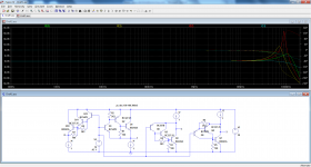
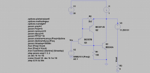
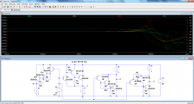
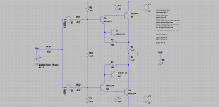
Here is a quick, informal test of the various options.
The triple, plain darlington is also shown for reference.
The devices are realistic, typical of such an application, and the DC bias current is 1A.
Some surprises: the pure D is not the one showing the least peaking (green trace).
The darlington-input variant is the winner (cyan trace), and unexpectedly the worst offender is not the full-sandwiched CFP (yellow), but the darlington-out one (red)
Offered for what it's worth: in order to draw definitive and general conclusions, a full analysis and discussion would be required....
Attachments
That's brilliant Elvee. That cyan trace (of the one circuit I hadn't thought of) is almost anomalously good. What I'm taking from this is that it may be acting as a high beta device as the wrap around. I'll test this myself and see if a single device with a changed BF does the same thing.
We also seem to have lost some capacitors on that one, with only 80 deg of shift at 200MHz. Does it go to 180 or 270 further up? It would be very neat if we have managed to lose one.
Something is very wrong with that darlington-out red trace. The phase seems to go the wrong way. Nothing comes to mind as to why that would be, but it's off the cards now. I like the look of the cyan trace and the topology is such that it seems to be inviting another power transistor in parallel.
... in order to draw definitive and general conclusions, a full analysis and discussion would be required....
Dear Elvee!
as usual,
what an elegant attitude!
as usual,
you are the first who found an early solution...
A three transistor emitter follower output was used commercially.
http://users.ece.gatech.edu/mleach/papers/tcir/tcir.pdf
http://users.ece.gatech.edu/mleach/papers/tcir/tcir.pdf
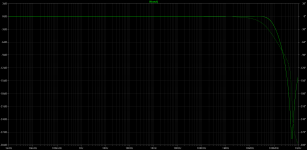

Yes, and it remains well-behaved at higher frequencies, see belowThat cyan trace (of the one circuit I hadn't thought of) is almost anomalously good.
Here is my interpretation: the small-signal, high(er) bandwidth darlington-in closes the loop around the slower output device, but since the transconductance is relatively low, the resulting composite is well-behavedWhat I'm taking from this is that it may be acting as a high beta device as the wrap around. I'll test this myself and see if a single device with a changed BF does the same thing.
The darlington-out configuration definitely seems problematic: it already shows in the pure darlington version, and becomes truly catastrophic in the CFP-in topology.Something is very wrong with that darlington-out red trace. The phase seems to go the wrong way. Nothing comes to mind as to why that would be, but it's off the cards now. I like the look of the cyan trace and the topology is such that it seems to be inviting another power transistor in parallel.
Something I find hard to explain is that the sandwiched version looks better; even the phase looks more consistent; there must be some subtle compensation mechanisms at play there
Attachments
Those rolloffs are too good to be true, of course, Padamiecki. But they are way better than the alternatives. As you say it definitely has potential. It's a very nice, soft, almost maximally flat second order for the most part. It does seem to speed up a bit later but only for the zero. That would seem to imply that we have managed to lose one of the capacitances, presumably by them being in series. Whether that works in real life is probably another question.
I wonder if there are some NPN vs PNP issues here too. We'd need to fake some parameters to keep them the same. I haven't done this simulation yet. I went to find a model for BD243 and 244 and then got carried away in something else. And they're not in my standard.bjt which has been blitzed by an update, losing all the Cordell and ztx models. So it all looked like a bit of work editing it again. (Yes I know that's not the ideal way to do it. 🙂 )
It is quite pleasing that the sandwiched CFP seems to work, because that's the one I thought might go off the scale. There was someone that Doug Self talked about in one of his more recent books doing a 3 transistor compound and there were some good reasons for it. I know that one of them for CFPs in general is that you can reduce the value of Re but I think this one had even more going for it? Any ideas what that was, anyone?
Thanks for getting this off on the right track Elvee.
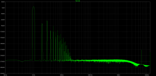
PS. Padameicki, are those harmonics correct? 60dB down in Class A for 2nd might sound very nice but doesn't seem an ideal starting point. Obviously it will get better with feedback but it doesn't look like the starting point for a four zero THD amplifier. (I should say that I've never simulated distortion on a Class A amp so don't actually know if this is good or bad.)
I wonder if there are some NPN vs PNP issues here too. We'd need to fake some parameters to keep them the same. I haven't done this simulation yet. I went to find a model for BD243 and 244 and then got carried away in something else. And they're not in my standard.bjt which has been blitzed by an update, losing all the Cordell and ztx models. So it all looked like a bit of work editing it again. (Yes I know that's not the ideal way to do it. 🙂 )
It is quite pleasing that the sandwiched CFP seems to work, because that's the one I thought might go off the scale. There was someone that Doug Self talked about in one of his more recent books doing a 3 transistor compound and there were some good reasons for it. I know that one of them for CFPs in general is that you can reduce the value of Re but I think this one had even more going for it? Any ideas what that was, anyone?
Thanks for getting this off on the right track Elvee.
PS. Padameicki, are those harmonics correct? 60dB down in Class A for 2nd might sound very nice but doesn't seem an ideal starting point. Obviously it will get better with feedback but it doesn't look like the starting point for a four zero THD amplifier. (I should say that I've never simulated distortion on a Class A amp so don't actually know if this is good or bad.)
Its an old oddity of amplifier design, adding lots of gain then having to kill it off again with capacitors to slow things down.
Better to just reduce gain to start with.
Single transistor VAS is sufficient.
Better to just reduce gain to start with.
Single transistor VAS is sufficient.
Single transistor VAS is sufficient.
I don't know if I am answering your point from exactly the perspective you are coming from but I don't think I agree with this. One of my worries in amplifiers (and I think it is among the reasons for people mistakenly liking low feedback designs) is that the gain in the VAS changes depending on the load. To me that necessitates a triple given that loudspeaker designers can't, or won't, serve us up with flat impedance curves. This is why John Curl uses a fet to pick up the output of the VAS and I think he is absolutely right.
In practical terms I'm not sure single transistors can give us the Betas we'd really like and I have often felt (and it is a feeling rather than really properly grounded) that CFPs get you past some of those failings. Another element I suspect it covers up for is the Early voltage. In an output stage this lets whatever is happening on the rails directly past the transistor, albeit at 72dB down - if it has a VAF of 100. I haven't actually modeled this (though I have seen the rail changes go straight through in simulations for a regulator) but I suspect that a CFP ameliorates this with its local feedback. (And note for above, I had forgotten that of course an EF also has its own local feedback). That probably gives less work for the feedback loop, or loops to do.
You are probably asking what this has to do with low overall feedback because I lost my train of thought. Well, smaller load resistors will of course vary that much less with changes in the load presented to them by the output stage. In many ways the worst thing you can do is have an active load. Certainly you will get the open loop gain but it will be mostly be used up in correcting how it, itself, changes. So, somewhere along the line in history, people realised that lower gain amps would sound better and put this down to lower feedback. I don't think it was anything of the sort, but I am happy to be disabused of my interpretation of what's going on. (I am also aware that a higher o/p impedance can soften things up to more of a valve sound but I am trying to keep that separate.)
Obviously you need enough gain through the amp to make feedback work properly.
My main point is why have lots of gain and then put in capacitors to slow things down again ?
I think its a matter of getting a happy medium.
My main point is why have lots of gain and then put in capacitors to slow things down again ?
I think its a matter of getting a happy medium.
I'm not sure quite what you are getting at here, Nigel.
I did a simulation very soon after LTSpice came out, on feedback, and you'd be astonished by how little you need to correct a wildly non-linear amp. It really was almost nothing. It's worth giving it a try because it does help to get things in perspective.
I did a simulation very soon after LTSpice came out, on feedback, and you'd be astonished by how little you need to correct a wildly non-linear amp. It really was almost nothing. It's worth giving it a try because it does help to get things in perspective.
I have seen with my own designs how non-linear transistors or very different output stage transistors can be made linear with feedback.
PS. Padameicki, are those harmonics correct? 60dB down in Class A for 2nd might sound very nice but doesn't seem an ideal starting point. Obviously it will get better with feedback but it doesn't look like the starting point for a four zero THD amplifier. (I should say that I've never simulated distortion on a Class A amp so don't actually know if this is good or bad.)
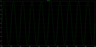
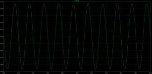
fft was correct,
I tried my favourite transconductance amp made of those tripples with gnfb, for small signals it is working good enough with ~400mA idle and 32mV offset, voltage sources are instead of the caps. For larger signals this amp needs more class A to work without major distortion.
Anyway the potential exists but how to use it is next thing...
Attachments

That's an interesting way of doing it. Thanks for uploading the .asc. I have got a model for the BD234/244 from OnSemi but it occurs to me that it won't necessarily be the same as the one you have. Nor does the one I've found agree with the Bourns datasheet. 🙂
A couple of things crossed my mind here. First, it will be interesting to see what it does with some big and lumbering power transistors. Will it really get them to move faster? You see I doubt this. The only thing that could be happening if there were signal at 25MHz is that it would all be coming from the drivers. The other thing was that we could try a Baxandall diode. Switch off is a problem with CFPs and that could help. Also, varying the value of the 100R, which again is there to help with switch off but is going to limit the current. On my regulator (which didn't have to worry about switch off) I started with 27R there and I think ended up with half that. That was into a ZTX653 with a TIP36C as the power transistor.
This switch off would be a good reason to do this in Class AB. I also want to look at the output impedance of the two halves and see how they match up. We could then just drop whatever DC we want onto the signal to use either half.
For the models perhaps we could standarise ourselves by using Bob Cordell's models, which are almost certainly more accurate than most - and perhaps we could use some more modern transistors. 🙂 Or if we want to stay with TO-220s, I've always rather liked the MJE15032C which is great value at about 70p each.
- Status
- Not open for further replies.
- Home
- Amplifiers
- Solid State
- A three transistor compound pair?