This paper is worth reading if you haven't already done so... Discussing dual radiation modes in flat panel speakers. Illustrates the concentrated local motion imposed on the panel by the exciter, superimposed on the reverberant modes away from the exciter location...
Damping dependent.
To a certain degree it illustrates what I was trying to get at with my comments to Leob
Eucy
Damping dependent.
To a certain degree it illustrates what I was trying to get at with my comments to Leob
Eucy
Attachments
Thanks Eucy, will check it out!
Did a quick test of the new plate, and is quite happy with the FR. Of course I introduced a couple of more differences. First of all I glued instead of using tape, and also did not round the corners since I now have a much better way of assembling the plates. However one more reason for rounding was that with the suspension points being in the center, the corners has so much excursion that it touches the frame corners.
I knew this might be a problem, but wanted to make sure, and it is easy with the current construction to fix that, and I can see how much it affects FR.
Here is FR with the corners and central suspension points in green and the prevision revision with suspension on long sides only in orange:

Again correlates quite well with Erics simulations. First mode moved up to around 130Hz, but that has given much better response in the region which actually matters to me. And the wierdness around 600-800Hz is gone. And HF is better, probably due to using glue. A couple of 5dB EQ adjusments and it will be close to my desired curve...don't think I will get much closer to ideal curve without putting in a lot of research.
Did a quick test of the new plate, and is quite happy with the FR. Of course I introduced a couple of more differences. First of all I glued instead of using tape, and also did not round the corners since I now have a much better way of assembling the plates. However one more reason for rounding was that with the suspension points being in the center, the corners has so much excursion that it touches the frame corners.
I knew this might be a problem, but wanted to make sure, and it is easy with the current construction to fix that, and I can see how much it affects FR.
Here is FR with the corners and central suspension points in green and the prevision revision with suspension on long sides only in orange:
Again correlates quite well with Erics simulations. First mode moved up to around 130Hz, but that has given much better response in the region which actually matters to me. And the wierdness around 600-800Hz is gone. And HF is better, probably due to using glue. A couple of 5dB EQ adjusments and it will be close to my desired curve...don't think I will get much closer to ideal curve without putting in a lot of research.
FYI
Smart Phone Screens Are About to Become Speakers
"Piezoelectrics enable displays to provide both high-quality audio and touch feedback"
Smart Phone Screens Are About to Become Speakers
"Piezoelectrics enable displays to provide both high-quality audio and touch feedback"
This is a nice paperThis paper is worth reading if you haven't already done so... Discussing dual radiation modes in flat panel speakers. Illustrates the concentrated local motion imposed on the panel by the exciter, superimposed on the reverberant modes away from the exciter location...
Damping dependent.
To a certain degree it illustrates what I was trying to get at with my comments to Leob
Eucy
Rounded the corners and got rid of the distortion, which is now at most 0.6%. It did affect the FR slightly, making it a bit less smooth in the low mid (red with rounded corners, green without):

That original green really looked good, and then along comes the red... nice job, congrats.Here is FR with the corners and central suspension points in green and the prevision revision with suspension on long sides only in orange:
View attachment 1278432
don't think I will get much closer to ideal curve without putting in a lot of research.
Eucy,Please do Eric... It'll be interesting to see how it fits with your theoretical results.
The tea gets a bit lively but it works quite well I found
Here's a pic of my latest effort, with tea, inspired by you.
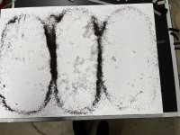
This was with an EPS panel. This EPS originally had some ridges on the surface from the wire cutting I suppose, and those ridges prevented the tea from moving around freely. So I sanded the ridges flat and tried again, but the sanding caused so much static that the tea wouldn't move at all! I used a damp rag to discharge the static, and it helped a lot, but some charge remained. That's why there is still tea even near the center of the middle area. I got frustrated with the static so gave up on the PS plate (at least for the time being). I played around with a cf/balsa plate for a bit too (with salt) but really only got one semi- interesting pattern (which I forgot to take a picture of). I have to come up with an arrangement (panel. supports, exciter placement) that will give several cool patterns from the same setup, but so far have not succeeded.
Can you share some pics of some of your Chladni efforts, Eucy?
Eric
Leob,I was a bit surprised that despite not having exact material properties, Erics FEA simulation seems to match quite well what I could see in the FR, so learning to do simulations seem like the best way to avoid having to test random placements hoping to hit the right spots 🙂
I do think that FEA simulation provides a lot of insights that are hard to understand otherwise. It's far from the whole story, but it's very worthwhile IMHO.
The software I use is LISA, which has a free version you can check out. It has only a limited number of nodes in the free version, but you can actually do a pretty decent simple plate model with it even with that limitation. And the full unlimited version is only CAD$99 (about US $74).
https://lisafea.com/
If you or anyone else wants to try it out, I would be very happy to provide suggestions to help you get started faster.
Below are the results for your plate (square corners, center mounts) using the free version (1st) and full version (2nd). As you can see, even with the free version, the model results are not the far off (with 5%). The mode shapes predicted are likewise pretty near identical. I'm honestly disappointed that more here aren't trying this.
Eric
I have made the decision to use 2-part epoxy glue instead of 'the tape' from the start.First of all I glued instead of using tape
Why risk the possibility of disconnection.
The fully cured glue WILL bond nicely to the existing tape 🙂
Yes please!Leob,
I do think that FEA simulation provides a lot of insights that are hard to understand otherwise. It's far from the whole story, but it's very worthwhile IMHO.
The software I use is LISA, which has a free version you can check out. It has only a limited number of nodes in the free version, but you can actually do a pretty decent simple plate model with it even with that limitation. And the full unlimited version is only CAD$99 (about US $74).
https://lisafea.com/
If you or anyone else wants to try it out, I would be very happy to provide suggestions to help you get started faster.
I've loaded LISA, but have not had much time yet to figure it out.
I used SolidWorks previously, but didn't get into the nitty-gritty very much.
Yes please!
I've loaded LISA, but have not had much time yet to figure it out.
Andre,
I'm glad to hear someone's interested! I've attached a small guide that I just put together a basic analysis with LISA. Please tell me if you find it useful or if anything doesn't work as expected, etc.
I can add instructions for adding perimeter supports and/or for isotropic materials and some other refinements, but I will wait to see if anyone finds this basic guide useful before I bother adding more.
Eric
Attachments
Eucy,
I did a few more Chladni figures yesterday, using my EPS plate and tea again. See images below. I'm still eager to see pictures of your (or anyone else's) Chladni figures.
Doing an impedance test first was really helpful, as it told me exactly what frequencies I needed to go to to get resonances.
One thing I was reminded of during this test was how "lobed" the sound field at a particular frequency is. Normally, I'm testing using frequency sweeps, so I don't usually have the driver running constantly at the same frequency like you do for making these figures. Anyway, I noticed again that if you set the driver to one of the resonances and start moving around, the sound volume varies quite dramatically with the location of your ears. At the resonances this effect is very pronounced. Now I'm curious if the effect is similar (or not) between resonances. I wasn't really thinking about that at the time...
Eric
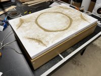
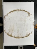
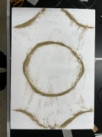
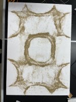
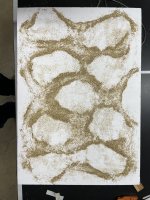
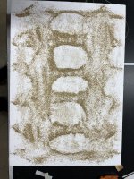


Ahhh Eric! ...How cool is that!.. 😁
There's just something magic about actually seeing the patterns in reality. I'd love to share some of mine, but I haven't done it for a fair while, and for the moment I can't find the photos. I'll do some more when I get time. It won't be for a while though, too much other stuff happening.
I'm happy the tea worked for you as well👍. The patterns show up well against the white EPS. After your initial problems, I was also thinking that you could try and blitz the tea to make it more powdery, but it doesn't look like it's necessary now.
It would be interesting to know the frequencies for each.
I was also a little surprised that the very first one you posted had quite tightly radiused corners..Quite a squashed pattern.
Another useful and fun tool in the kit.
Cheers
Eucy
The other thing I should mention is that this process is also useful for checking the effects of moving the exciter location. Set the rig high enough to reach under and just hand hold the exciter as you move it around.
Eucy
Eucy
Thanks EricI can add instructions for adding perimeter supports and/or for isotropic materials and some other refinements, but I will wait to see if anyone finds this basic guide useful before I bother adding more.
That was easy but I had to chop the size down to fit the 1300 node limit. Also it doesn't handle anisotropy in the vibration mode.
I would be interested in your extra info to need about with it
Cheers
Eucy
Thanks Eric!Andre,
I'm glad to hear someone's interested! I've attached a small guide that I just put together a basic analysis with LISA. Please tell me if you find it useful or if anything doesn't work as expected, etc.
I can add instructions for adding perimeter supports and/or for isotropic materials and some other refinements, but I will wait to see if anyone finds this basic guide useful before I bother adding more.
Eric
It took me a few minutes to figure out how to run less than 1300 nodes (demo limit), so I've run the model with 50 nodes but with only a 20 x 15 mesh.
My 7th mode is the same shape as the 7th mode in your tutorial. But a different frequency, 505.3Hz vs 67.0Hz (I'm assuming Hz??)
1. Why the difference? Surely the mesh resolution doesn't change the modal charateristics?
2. How do I set up driver characteristics and positioning?
3. Ditto edge treatment.
Thanks for your time.
A.
1/... Smaller size panel = higher frequency/mode1. Why the difference? Surely the mesh resolution doesn't change the modal charateristics?
2. How do I set up driver characteristics and positioning?
3. Ditto edge treatment.
Thanks for your time.
A.
2/ Not sure that Lisa can easily handle forced vibrations (if at all)
3/ If it can do me than free/simply supported/fully restrained, you'd have to model spring constraints or similar
Eucy
Looking to the future:
--- Metamaterials
https://dukespace.lib.duke.edu/items/4bd7f68d-9643-41e3-95c2-c49a82f05156
If anyone would have access to the aforementioned paper prior to free release date, please share.
--- Transverse sound wave:
https://www.sciencedaily.com/releases/2021/12/211207152541.htm
The thesis (from https://www.sciencedirect.com/science/article/abs/pii/S0307904X20302742)
"The micropolar elasticity introduces the extra microrotation field, and thus, the relative rotation in the local resonance structure can be included naturally. On the other hand, porous and composite materials with reinforced particles or fibers have various microstructures. The microstructure effects are usually ignored when focus is given to the local resonance structure. However, the microstructure effects cannot be ignored when the wavelength is comparable with the characteristic length of the microstructure. In fact, four kinds of vibration modes (resulting from the coupling between the micro-displacement and the micro-rotation) are predicted by the micropolar elasticity, however only two modes (longitudinal and transversal models) exist in the classical elasticity. The use of the micropolar elasticity can involve the microstructure effects of the material and further the interaction between the material microstructure and the local resonance structure.
In this paper, the micropolar elastic metamaterial composed of the micropolar elastic host material and the periodically arranged local resonators on the surface of the host material are further considered. By introducing the additional translation and rotation displacement fields, a continuum model of micropolar elastic metamaterial is presented to characterize the resonance behavior of the local resonance structure and the material microstructure effects of the repeating unit cell (RUC). Different from the preceding works [1–5,10,11] and the author's previous work [12], the micro-rotation and the relative rotation were included in the present work due to the micro-rotation field existing in the micropolar material. The wave propagation behaviors, the dispersion feature and the wave band gaps phenomenon in such a micropolar metamaterial are investigated."
Great!1. Why the difference? Surely the mesh resolution doesn't change the modal charateristics?
2. How do I set up driver characteristics and positioning?
3. Ditto edge treatment.
1. You must have entered 0.25 for the thickness instead of 0.025. Regarding mesh size, a tighter mesh (more elements) gives a more accurate solution, but even a coarse mesh with 300 elements (15x20) gives results within a few %.
2. Sadly, driver characteristics are beyond the capabilities of this model. That feels really limiting, I realize. but note also however that:
- I have observed that for most of the plates and exciter combinations that I have used, adding an exciter doesn't have much effect on the values (Hz) of the natural frequencies. Often adding an exciter will shift the fundamental upwards by a few hz, and modal frequencies above that are even less affected, if at all. I say this based on literally hundreds of "tap" tests and impedance tests. One caveat to the above is that I'm talking about cases where the exciter resonance (fixed VC, free magnet) is low compared to the panel's fundamental resonance.
- You can still infer a lot about the effect of driver location from the results of the model even if the driver isn't explicitly in the model. Basically, you can assume that if the driver is placed in an area that is dark blue in the simulation for a particular mode, that mode will not be excited (i.e. activated) by the driver. Conversely, if a driver is placed in an area that is red in the simulation for a particular mode, that mode will be very effectively excited (activated) by the driver.
Eric
- Home
- Loudspeakers
- Full Range
- A Study of DMLs as a Full Range Speaker