Hello LeobCame across mention of using Zobel networks to neutralize inductance of a voice coil. Anyone has thoughts about using that with the larger exciters to get better HF response?
Can it really be so simple that I just need to add a capacitor and a resistor to the exciters to make them good for full range?
Unfortunately not. This kind of circuit is used to avoid the amplifier to see the inductance. It is used also in passive crossover to transform the loudspeaker impedance in something similar to a resistance. Not a solution in your case.
Christian
Hello SteveChristian.
my good recording apps without AVC were on my broken phone,I was just testing to see if it up loaded ok.
it is not easy to record speakers in an ordinary room.
normally I would have to make a recording then listen to it on my headphones to see how it sounded and then adjust the position of the microphone until I get the sound right ,this could take a few recordings.
I would also have to adjust the sub as well.
It is a compromise of getting as little of the room sound as possible, but not getting too close to the speakers.
If you get too close you tend to loose the ambience, and it starts to sound a little closed in.
If you set up the sound to what you think is good by ear before recording , I found that the microphone picks up strange sounds that our brains seem to ignore ?
When I first started recording my panels I'd make the recording thinking they sounded great, but when I played It back It sounded like I recorded It in the bathroom !!
It makes you understand why they have recording studios.
I new the sound was not right with the last zip recording ,but that is all I have at the moment, until I get a new phone,
I only hope it sounds as good as my old galaxy note 4 ?
Steve.
Ps.
You are correct about the channel volume levels, I noticed this on my old phone as well.
It might be a phone thing ?
I understand your are adjusting your record procedure. No problem. The result was even quite good.
Phones are able to make good record but here the goal is to have excellent records to reflect the quality of very good system. In itself it is a challenge and might be a full field of research...
I made a simple test which was to listen with a headphone the sound collected by the measurement mic I use (usb Umik1). It is like you are in an other room.
Then I purchase a Zoom H1n hand recorder. You can plug on it external mic and also an headphone.
With the mic it has, I haven't pushed the test because it is cardioid mics and the electronic noise floor is a bit too high. I don't want and I can't (neighbors) push the level very high.
Then I added to external omni mics.
If they are close one to the other, the sound is very different from what we here.
If they are separated by let say 20 or 30cm, you get something more realistic.
I see on my phone that on mic is at the top, the second at the bottom on the short sides so 15cm between them.
When you record, is the phone horizontal with the long side perpendicular to the loudspeaker direction?
About the gain, nothing says what the phone maker or the app designer does... Recording high quality stereo signals is probably at the limit even out the field of specifications.
Some suggestions :
- Make record and then a second rotating the phone by 180° (Left mic becomes Right) with same track, same volume to see if the gain reduction "follows" the mic. If yes a volume correction by Audacity is possible.
- Have a look to "Jenklin disk". Perhaps you already know it... It is a record technic with a disk (30cm diameter ) between 2 mics. I remember a video where different materials were tested. It was said good results are possible with simple cardboard. So why not having your phone going through a disk, one mic on each side...
Anyway it is an interesting technique to share results.
Christian
It might be more complex... Or even it is more for sure...The wattage is simply the power rating of the exciter meaning how many watt inside before it reaches the maximum temperature that is allowed by its components ( voice coil material, internal glue, wire insulating material...). The distortion and the mechanical behavior (displacement) is linked to the panel design. For now, nothing say which limit is reached first.Distortion....I think it takes more than a couple of hundred watt to make anything more spectacular than that happen 🙂
However I just realized I have not yet tried using two 50w exciters on one EPS panel. With a single exciter I have to turn the amp up over 70% to start noticing distortion...at which level the amp of course is expected to start distorting as well. But with both exciters on one panel I should be able to get similar wattage as 4x DAEX25FHE-4.
There is another important parameter which is the force factor BL which is the link between the current and the mechanical force. Without knowing the force factor, you can't compare exciters. Imagine one with a very low BL, the second with a very high. You will perhaps input the max power in the first one for a low SPL while the second we'll be limited by the displacement. The force factor is a key point in the efficiency.
I came across a post in the parts-express forum that claimed to tried it on a Dayton Thruster, which also suffers from high inductance, and he claims that it helped with the HF extension.Hello Leob
Unfortunately not. This kind of circuit is used to avoid the amplifier to see the inductance. It is used also in passive crossover to transform the loudspeaker impedance in something similar to a resistance. Not a solution in your case.
Christian
I know that is not normally the reason to use it, but unless that poster is lying it should help.
I know the wattage is not everything, but it is the parameter available that has closest correlation to how much SPL it can produce.It might be more complex... Or even it is more for sure...The wattage is simply the power rating of the exciter meaning how many watt inside before it reaches the maximum temperature that is allowed by its components ( voice coil material, internal glue, wire insulating material...). The distortion and the mechanical behavior (displacement) is linked to the panel design. For now, nothing say which limit is reached first.
There is another important parameter which is the force factor BL which is the link between the current and the mechanical force. Without knowing the force factor, you can't compare exciters. Imagine one with a very low BL, the second with a very high. You will perhaps input the max power in the first one for a low SPL while the second we'll be limited by the displacement. The force factor is a key point in the efficiency.
Of course in the end I will test it, but if the plate cannot handle 100w from one one type of exciter, I think it is fair to assume it is unlikely to handle 80w of another exciter. That assumption might very well be off in some cases, but is good enough for informing my decision what exciter setup to try next.
The zobel network might help the amplifier to manage the load. To correct the root case I think no. Easy to test.. just a resistor around 4 Ohms and the right capacitor. I can't do it, I don't have exciters with high inductance. Could you?I came across a post in the parts-express forum that claimed to tried it on a Dayton Thruster, which also suffers from high inductance, and he claims that it helped with the HF extension.
I know that is not normally the reason to use it, but unless that poster is lying it should help.
Steve,Christian.
my good recording apps without AVC were on my broken phone,I was just testing to see if it up loaded ok.
it is not easy to record speakers in an ordinary room.
normally I would have to make a recording then listen to it on my headphones to see how it sounded and then adjust the position of the microphone until I get the sound right ,this could take a few recordings.
I would also have to adjust the sub as well.
It is a compromise of getting as little of the room sound as possible, but not getting too close to the speakers.
If you get too close you tend to loose the ambience, and it starts to sound a little closed in.
If you set up the sound to what you think is good by ear before recording , I found that the microphone picks up strange sounds that our brains seem to ignore ?
When I first started recording my panels I'd make the recording thinking they sounded great, but when I played It back It sounded like I recorded It in the bathroom !!
It makes you understand why they have recording studios.
I new the sound was not right with the last zip recording ,but that is all I have at the moment, until I get a new phone,
I only hope it sounds as good as my old galaxy note 4 ?
Steve.
Ps.
You are correct about the channel volume levels, I noticed this on my old phone as well.
It might be a phone thing ?
which App do you use? I had a look to this topic and it is not clear for me that all the app use both mic...
Did some tests with two 50w exciters on a Neopor 500x330x25mm. I really need to work on a good suspension solution, the plate is starting to behave quite wildly!
I don't have the distortion measurements with one exciter to compare with, but my impression is that plate perhaps starts reaching a limit, and distortion becomes obvious at around 60% power, slightly earlier than before. Hard to say when listening at those levels though, and cannot measure since with over 50% power REW will abort the test due to excessive clipping, so as expected the mic cannot handle the SPL.
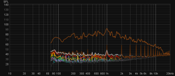
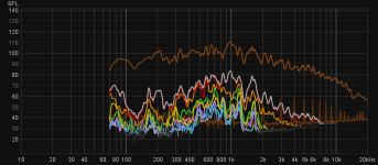
Attached are distortion graphs for 25% 40% and 50% power. Also attached is my Tannoy Reveal 802 at 50% as reference (although a bad one, since they are active speakers, so not using same amp as for the plates). It is clear that around 50% distortion is starting to become a problem, both for the plate and the Tannoys.
I don't have the distortion measurements with one exciter to compare with, but my impression is that plate perhaps starts reaching a limit, and distortion becomes obvious at around 60% power, slightly earlier than before. Hard to say when listening at those levels though, and cannot measure since with over 50% power REW will abort the test due to excessive clipping, so as expected the mic cannot handle the SPL.
Attached are distortion graphs for 25% 40% and 50% power. Also attached is my Tannoy Reveal 802 at 50% as reference (although a bad one, since they are active speakers, so not using same amp as for the plates). It is clear that around 50% distortion is starting to become a problem, both for the plate and the Tannoys.
Attachments


I was surprised by the claim as well, seems a bit too good to be true. But also, it is not that the coil cannot reproduce HF content. I can EQ out the HF, and it is reproduced, only at lower level.The zobel network might help the amplifier to manage the load. To correct the root case I think no. Easy to test.. just a resistor around 4 Ohms and the right capacitor. I can't do it, I don't have exciters with high inductance. Could you?
I don't have a non polarized caps, but will order some to try out.
If it does work it seems like a bit of a silver bullet for DML, since the voice coil inductance seems to be much more of an issue. For a tweeter you don't need a long coil anyway, and for a woofer you don't need the HF response, so the inductance is not really an issue in the same way.
Leob,I was surprised by the claim as well, seems a bit too good to be true. But also, it is not that the coil cannot reproduce HF content. I can EQ out the HF, and it is reproduced, only at lower level.
I don't have a non polarized caps, but will order some to try out.
If it does work it seems like a bit of a silver bullet for DML, since the voice coil inductance seems to be much more of an issue. For a tweeter you don't need a long coil anyway, and for a woofer you don't need the HF response, so the inductance is not really an issue in the same way.
I just found those 2 papers that at first glance seems good on the Zobel topic
- Zobel Network Design
- Loudspeaker Voice-Coil Inductance Losses: Circuit Models, Parameter Estimation, and Effect on Frequency Response
For a short test without pushing the power, 2 standard 22µF in series with their + connected together should do the job
Interesting... We don't have many posts about the distortion. Thank youDid some tests with two 50w exciters on a Neopor 500x330x25mm. I really need to work on a good suspension solution, the plate is starting to behave quite wildly!
I don't have the distortion measurements with one exciter to compare with, but my impression is that plate perhaps starts reaching a limit, and distortion becomes obvious at around 60% power, slightly earlier than before. Hard to say when listening at those levels though, and cannot measure since with over 50% power REW will abort the test due to excessive clipping, so as expected the mic cannot handle the SPL.
Attached are distortion graphs for 25% 40% and 50% power. Also attached is my Tannoy Reveal 802 at 50% as reference (although a bad one, since they are active speakers, so not using same amp as for the plates). It is clear that around 50% distortion is starting to become a problem, both for the plate and the Tannoys.
If, at about the same SPL level, both distortion are similar, it is a very good point.
Have you checked the distortion spectrum content for both : H2 and H3? DML are said having H2. There are papers saying we like H2 and distortion spectrum with a nice decreasing in the harmonics.
What is the "red" curve with spikes at 2k, 3k...? I am still with the previous REW version!
This is the legend for the graphs:Interesting... We don't have many posts about the distortion. Thank you
If, at about the same SPL level, both distortion are similar, it is a very good point.
Have you checked the distortion spectrum content for both : H2 and H3? DML are said having H2. There are papers saying we like H2 and distortion spectrum with a nice decreasing in the harmonics.
What is the "red" curve with spikes at 2k, 3k...? I am still with the previous REW version!
I came up with a bit different figure, following the basic version in this:Leob,
I just found those 2 papers that at first glance seems good on the Zobel topic
Basically C = L/R². So 8Ohm/0.8mH => 12.5µF. You are right non polarized.
- Zobel Network Design
- Loudspeaker Voice-Coil Inductance Losses: Circuit Models, Parameter Estimation, and Effect on Frequency Response
For a short test without pushing the power, 2 standard 22µF in series with their + connected together should do the job
https://audioxpress.com/article/voice-coil-lab-notes-improved-zobel-network
Where C = L/(R*1.25)²
DC impedance is 7.8 ohm, so C = 7.8/(0.8*1.25)²
I'm hoping that a 10µF should do regardless.
Thank youDid some tests with two 50w exciters on a Neopor 500x330x25mm. I really need to work on a good suspension solution, the plate is starting to behave quite wildly!
I don't have the distortion measurements with one exciter to compare with, but my impression is that plate perhaps starts reaching a limit, and distortion becomes obvious at around 60% power, slightly earlier than before. Hard to say when listening at those levels though, and cannot measure since with over 50% power REW will abort the test due to excessive clipping, so as expected the mic cannot handle the SPL.
Attached are distortion graphs for 25% 40% and 50% power. Also attached is my Tannoy Reveal 802 at 50% as reference (although a bad one, since they are active speakers, so not using same amp as for the plates). It is clear that around 50% distortion is starting to become a problem, both for the plate and the Tannoys.
It just had a quick look on the FR and distortion of the small panel I am testing : the THD is mainly based on H2. Seems there are peaks locally with much higher level of distortion. To see if we could link that to modes.
May I suggest you have a look to the noise floor. The spikes each 1kHz are noise. Not sure they have an impact on the over all measures... nevertheless they have nothing to do here. Do you run the test with a laptop? If yes have look using it on the battery. It might be some noise from a switching power supply, an halogen floor lamp variator?
The spectrum below are not shown because relevant of a good panel or even a good measurement. It is just some tests on going to help in understanding DML, REW use and so one.
This leads me to think for next steps for material evaluation we might decide to get the distortion for a given SPL (70dBA?), and the spectral contamination at also a common level.
Here are FR (fundamental), THD (black) and noise floor (brown)
Here FR, H2 (red) and H3 (orange)
Thank you Leob for the link. To keep. Much simpler than the previous one.I came up with a bit different figure, following the basic version in this:
https://audioxpress.com/article/voice-coil-lab-notes-improved-zobel-network
Where C = L/(R*1.25)²
DC impedance is 7.8 ohm, so C = 7.8/(0.8*1.25)²
I'm hoping that a 10µF should do regardless.
The behavior of the voice coil is not exactly modeled by a simple inductance a good practice is to have a the resistance is a bit higher than the DC resistance. I did that years ago for passive crossovers.
So 1.25 is probably a good rule of thumb considering the source.
So yes 10Ohm and 10µF. It is not really sensitive.
I suggested 2 polarized capacitors 22µ in serie so in theory 11µF for a quick test
For the formula (if somebody comes back to it later)
C = L/(1.25*R)² so C=0.0008/(1.25*8)²=10µF
Don't have much in the way of components at hand.Thank you Leob for the link. To keep. Much simpler than the previous one.
The behavior of the voice coil is not exactly modeled by a simple inductance a good practice is to have a the resistance is a bit higher than the DC resistance. I did that years ago for passive crossovers.
So 1.25 is probably a good rule of thumb considering the source.
So yes 10Ohm and 10µF. It is not really sensitive.
I suggested 2 polarized capacitors 22µ in serie so in theory 11µF for a quick test
For the formula (if somebody comes back to it later)
C = L/(1.25*R)² so C=0.0008/(1.25*8)²=10µF
Not having any luck finding a suitable resistor either. Not really sure what wattage I will need, but looking for 10-30w, the ones I do find are a bit costly.
Christian.
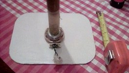
This bracing on an art panel is only 1cm by 2cm and does not badly affected the sound from the exciter and panel.
The other picture is of the sort of mounting I would use for my card or veneer panels, this would leave the dml panel totally free floating only supported by the coil spider.
This is a 25mm wood dowel ,this would be attached to whatever I chose to mount onto.
The card coated in epoxy only weighs 25g ,is balanced and puts very little strain on the exciter coil spider.
Steve.
Attachments

hi guys.. any one tried using a CD/DVD as in below video.. that person saying its acting like a tweeter on those canvas panels.. in his earlier videos he had used the cd/dvd on the back of the panel attached to the plywood base where exciter was attached .. here in this one , its attached on the front of the canvas panel..
Tried no, think about using a CD as a central piece yes but I can't say for which reason I didn't do it... perhaps simply because of the weight of the CD which is not in the range of material with a good efficiency (acrylic?). An other reason is probably also I don't have a lack of treble with plywood or the canvas panel.hi guys.. any one tried using a CD/DVD as in below video.. that person saying its acting like a tweeter on those canvas panels.. in his earlier videos he had used the cd/dvd on the back of the panel attached to the plywood base where exciter was attached .. here in this one , its attached on the front of the canvas panel..
Creativity around the DML is probably almost endless. A minimum of characterization and analysis are necessary.
also one more question.. can we use any plywood for full long big plywood DML or for putting on the back of canvas panel ? or do we need some thing like poplar or bitch ply as being used here.. (means do we need plywood of certain quality like void free plywood or material etc) ?Tried no, think about using a CD as a central piece yes but I can't say for which reason I didn't do it... perhaps simply because of the weight of the CD which is not in the range of material with a good efficiency (acrylic?). An other reason is probably also I don't have a lack of treble with plywood or the canvas panel.
Creativity around the DML is probably almost endless. A minimum of characterization and analysis are necessary.
when compared with full long plywood one and canvas one , would it be good if we go for canvas one as its looking smaller/lighter and compact, if not much of difference in sound...
- Home
- Loudspeakers
- Full Range
- A Study of DMLs as a Full Range Speaker