Yeah that's the circuit I was thinking of. Pin5 can be 8V with TDA1543, on TDA1387 you'll likely destroy the chip. If using 8V on 1543, you'll want the TL431 to set a higher voltage, about 6V.
For 16X parallel it would work too, just lower the 1k1 suitably to cope with 16*2.3mA for the current swing.
For 16X parallel it would work too, just lower the 1k1 suitably to cope with 16*2.3mA for the current swing.
It seems to me the TDA1543 is indestructible 😀
Once I placed it in the socket wrong way and left it sucking 1A for minutes. Checked the temperature and got a blister. Worked perfectly afterwards! 😀
(1K1 ÷ 16 should do...)
I'll try this circuit and let you know asap. Thanks!
Once I placed it in the socket wrong way and left it sucking 1A for minutes. Checked the temperature and got a blister. Worked perfectly afterwards! 😀
(1K1 ÷ 16 should do...)
I'll try this circuit and let you know asap. Thanks!
Last edited:
Hello Abraxalito,
received components and starting assembly of the active stage you suggested.
Trying out a single TDA1543 to keep things simple (for now).
Can you remove my doubt about pin7 (Vref) : still goes to ground with 1.5K, correct ?
Thanks B.
received components and starting assembly of the active stage you suggested.
Trying out a single TDA1543 to keep things simple (for now).
Can you remove my doubt about pin7 (Vref) : still goes to ground with 1.5K, correct ?
Thanks B.
You're using the single transistor I/V on TDA1543? In which case yes you need some bias (by a R on pin7) just as before. But you can get better sound by using your own supplied current source rather than using the one internal to the 1543.
Yes ! I'm wiring up the schematic you suggested here
(Single PNP transistor in common-base mode.):
http://www.diyaudio.com/forums/digi...elp-noob-building-9028-dac-2.html#post5256178
My own supply current you say ? I'll do it. Can you give me more details on how to do it ? Thanks.
(Single PNP transistor in common-base mode.):
http://www.diyaudio.com/forums/digi...elp-noob-building-9028-dac-2.html#post5256178
My own supply current you say ? I'll do it. Can you give me more details on how to do it ? Thanks.
Right now, no I feel too lazy to draw a schematic. Use the resistor on pin7 😀
I didn't say 'your own supply current' rather 'your own supplied current source'.
I didn't say 'your own supply current' rather 'your own supplied current source'.
Ok ok no worry 🙂 I have abused of your patience already.
I will complete what is settled.
"There's plenty meat on the fire already" 😀
Will have the desert later...
Thanks again !
I will complete what is settled.
"There's plenty meat on the fire already" 😀
Will have the desert later...
Thanks again !
Hello Abraxalito,
I've built the circuit you suggested.
("Single PNP transistor in common-base mode. DAC output goes to emitter, I/V resistor between collector and 0V." for TDA1543)
It sounds divine !! Much better than the single TDA1543 or 24x TDA1543 with Output resistance to ground. Really appreciated the tip !
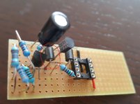
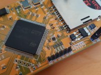
I'm only having this little trouble: It played fine for a few minutes, then there was a pop and it when virtually quiet. After testing for everything else I figured maybe there was trouble with the BC807. I replaced it and it played fine again! After a few mintes it went quiet again. 😀 (Attached are the components I'm using; After Ferrite Bead we have a healthy +3.79V)
What am I doing wrong ?
I've built the circuit you suggested.
("Single PNP transistor in common-base mode. DAC output goes to emitter, I/V resistor between collector and 0V." for TDA1543)
It sounds divine !! Much better than the single TDA1543 or 24x TDA1543 with Output resistance to ground. Really appreciated the tip !
I'm only having this little trouble: It played fine for a few minutes, then there was a pop and it when virtually quiet. After testing for everything else I figured maybe there was trouble with the BC807. I replaced it and it played fine again! After a few mintes it went quiet again. 😀 (Attached are the components I'm using; After Ferrite Bead we have a healthy +3.79V)
What am I doing wrong ?
Attachments
![20180408_163851[1].jpg](/community/data/attachments/623/623293-8782799c3de67a8961a393c4b7e48cdd.jpg?hash=h4J5nD3meo)
![20180408_164416[1].jpg](/community/data/attachments/623/623307-e23da37bdf5431b027b40cb18066227e.jpg?hash=4j2je99UMb)
How are you generating the reference voltage to feed to the bases?
Its possible you've got oscillation - try putting 220ohm resistors between the Vref and the base of each transistor. I think my original schematic had a ferrite bead on the base but that's not enough to suppress oscillation in every condition.
Its possible you've got oscillation - try putting 220ohm resistors between the Vref and the base of each transistor. I think my original schematic had a ferrite bead on the base but that's not enough to suppress oscillation in every condition.
Hello !
I am strictly following your schematic (+3.8V from TL431, and pulling the +6V from the power supply - the same one feeding the TDA1543)
http://www.diyaudio.com/forums/digi...elp-noob-building-9028-dac-2.html#post5256178
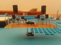
Yes! your original schematic has a ferrite bead on the base. I marked it red in my photo (too small?).
Ok I'll try the 220ohm asap ( and get some spare BC807s 🙂 )
Thanks!
B.
I am strictly following your schematic (+3.8V from TL431, and pulling the +6V from the power supply - the same one feeding the TDA1543)
http://www.diyaudio.com/forums/digi...elp-noob-building-9028-dac-2.html#post5256178
Yes! your original schematic has a ferrite bead on the base. I marked it red in my photo (too small?).
Ok I'll try the 220ohm asap ( and get some spare BC807s 🙂 )
Thanks!
B.
Attachments
Last edited:
Ah OK, I got a bit confused because I wondered where the TL431 was. But now I see you've only built up one channel, the 'transistor' bottom left is actually the TL431 right?
Yes, bottom left is the TL431 !
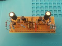
Meanwhile I've added the second channel (it's a bit neater) 🙂
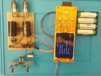
Here's a few pictures of the complete setup, with "plug ins" next to their seat.
(the two extra 8 pin holders are for components that are not in use)
The TDA1543 is under the little alluminum heatsink. I use this board also for the 24x.
( Waiting to buy BC807s 😀 )
Meanwhile I've added the second channel (it's a bit neater) 🙂
Here's a few pictures of the complete setup, with "plug ins" next to their seat.
(the two extra 8 pin holders are for components that are not in use)
The TDA1543 is under the little alluminum heatsink. I use this board also for the 24x.
( Waiting to buy BC807s 😀 )
Attachments
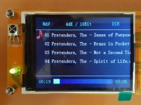
Interesting that you're using the same SD card player that I've had my eye on for a while. From 'College Audio Store' in Aliexpress?
Actually I bought it on ebay, but this is the one that is having static between tracks,
so I would not recommend it. I am actually looking into this one:
PJRC Store
It is 44.1Khz 16 bit, I2S ouput, can be slaved (!), and has a "play wav" library ready.
I'll write some code as soon as I get the screens.
so I would not recommend it. I am actually looking into this one:
PJRC Store
It is 44.1Khz 16 bit, I2S ouput, can be slaved (!), and has a "play wav" library ready.
I'll write some code as soon as I get the screens.
I think everything important is on this page:
Audio Library, for high quality sound input, processing and output on Teensy 3
Audio Library, for high quality sound input, processing and output on Teensy 3

Hello Abraxalito,
please correct me if have misunderstood you: I've added two 220ohms between Vref ( TDA1543's pin7 ) and each transistor's base (BC807), next to the ferrite bead.
Something is not right though: all is silent, the circuit's consumption (including the TDA1543) rises from 0.04A to 0.10A and the +3.8V at the (transistor's) base drops to 2.9V. If I remove the 2 resistances, it plays fine, but I keep it short not to burn the transistors again 😀
thanks 🙂
B.
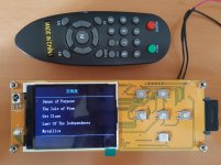
Ps here's the player if you want a closer look.
What SD card are you using with that SD player - I suspect that might be your problem - it requires a fast HC SD card
"Only supports a subdirectory, only supports 32GB of memory card (memory card must be CLASS6 and above, must be a HC card)."
I know 2 people who have this same SD player & no static although clicks & pops if a slow SD card i sused
Last edited:
Did you leave the ferrite bead in circuit? What my intention was for you to replace the ferrite with the 220R resistor. I can't see why adding the resistors in parallel with the bead would change anything at all. So you're right, something's definitely not right. Power consumption of 100mA is also not at all right. With the TL431 voltage dropping it tends to indicate you didn't connect the resistor in parallel with the bead, rather it went some place else...
BTW, Bart, do you have a link where you bought on ebay - I see it comes with remote control but I don't see that remote with any other offerings?
I just want to get the IR codes sent for each of the buttons: up, down, left, right & play/stop. You don;t happen to have an IR learning device, do you?
I just want to get the IR codes sent for each of the buttons: up, down, left, right & play/stop. You don;t happen to have an IR learning device, do you?
- Status
- Not open for further replies.
- Home
- Source & Line
- Digital Line Level
- A story of mysterious interaction between a diy tda1543 dac setup and the human body.