A quick update for the anyone who might be interested.
I did find that the transformer was not too sensitive to driving source impedance and reduced the source impedance to the primary winding to 500 ohms which resulted in a rather significant improvement in the behavior at 20kHz.
FR:
Noise:
The breadboard is without doubt the worst I have ever done, but there is a grounded copper foil shield under both boards connected directly to the safety earth (as is the pre-amplifier proper). The transformer does not radiate much of a field. On the bench there was no measurable mains spectra on the outputs at all, and no audible hum or buzz despite the terrible breadboard design. (It was not originally intended for listening tests and I just stuck the pots and I/0 in the only available space - it's all screwy.)
Next step is to design a suitable box and have it fabricated. I've ordered a nice 48 step 50K ladder attenuator for it.
Four of my friends are currently building their own copies, hopefully they'll post their experiences here.
I did find that the transformer was not too sensitive to driving source impedance and reduced the source impedance to the primary winding to 500 ohms which resulted in a rather significant improvement in the behavior at 20kHz.
FR:
- 1Vrms it is flat within +/1dB from 10Hz - 100kHz
- 2Vrms is flat within +/-1dB from 20Hz - 100kHz
- At 2Vrms flat from 20Hz - 18kHz +/-0.1dB, -0.6dB @ 20kHz
- <= 0.007% THD (80kHz LPF) at 4Vrms from 50Hz - 10kHz.
Noise:
- <100uVrms unweighted broadband (2MHz measurement bandwidth) no discernible hum or ripple present on the output.
The breadboard is without doubt the worst I have ever done, but there is a grounded copper foil shield under both boards connected directly to the safety earth (as is the pre-amplifier proper). The transformer does not radiate much of a field. On the bench there was no measurable mains spectra on the outputs at all, and no audible hum or buzz despite the terrible breadboard design. (It was not originally intended for listening tests and I just stuck the pots and I/0 in the only available space - it's all screwy.)
Next step is to design a suitable box and have it fabricated. I've ordered a nice 48 step 50K ladder attenuator for it.
Four of my friends are currently building their own copies, hopefully they'll post their experiences here.
Attachments
I will be posting build progress for an actual full featured line stage using this design starting around December 20th. (I've promised myself to hold off until then since it is supposed to be a holiday activity.)
I will use the prototype boards that will be going into this line stage several times a week and am happy with the subjective performance in this application. I've shared sufficient measurements I think.
- Includes 59 step ladder attenuator
- Balanced outputs/unbalanced outputs either floating or audio GND referenced
- Switchable output polarity in both modes with mute
- One set of balanced inputs (input transformers
- Two sets of unbalanced inputs
I will use the prototype boards that will be going into this line stage several times a week and am happy with the subjective performance in this application. I've shared sufficient measurements I think.
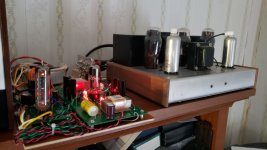
So I finished the project today, having ordered a custom chassis box from Par Metal some weeks ago. The final assembly occurred over a period of about 9 hours. This is what I refer to as a slapdash build - goal to get it technically correct and done in a short time period so it's not really all that pretty inside. The biggest problem really was figuring out how maintain reasonable distance between that oversized power transformer and the audio board.
It has floating balanced and unbalanced outputs, two unbalanced inputs, a balanced input. (Need to order some transformers from Lundahl as using the A20s I had planned on would have resulted in some really undesirable placement compromises with the power transformer.
There is no audible hum on the outputs (basically all the same as previously measured), no changes in performance were noted.
It looks a bit like a bit of laboratory gear. From left to right, power + led, mute and polarity reverse switches, stepped attenuator, and source selector.
Total power consumption is under 20W.
Great stuff Kevin,
I had played around with the 6n6p for a few years, as both a DAC output and as a driver for power stages. Always push/pull or differential stages, never messed with SE. It did its job well - I particularly liked the low Rp, internal shield, easy-to-use grid bias level, and intelligent pinout making for clean wiring. It does seem to operate best with lots of plate current. 6mA is a minimum as a small signal stage, but I have run as high as 22 mA.
Sounds like the Rp is not problematic for you with the parafeed design - I am a bit surprised by this, particularly given the Lundahl transformer, but then again I have not tried the 1930. Their push pull types are finicky with resonances, I suspect largely due to the multi-layered construction - lots of places for strays to pop up. Maybe the 1930 is much less complex in its build.
When you go about designing the PS, take care that when using the mu output of the cascode CCS, your PSRR is poor, and I typically get too much 120Hz leaking through for my preference. I always end up preferring the lower output. I predict, given the 6n6p low Rp, you will not gain any benefit with the use of mu output. This is not driving a 300B, after all. My latest favorite is a series CCS driving a glow tube(s) for the low ripple B+ of your choice.
Very interested in seeing final FFT measurements, so I can compare to my earlier designs 🙂
Hi Zigzag,
Not sure whether you read the rest of the thread, most of the details involving the design process are in prior posts. I found that the LL1930 when driven by the recommended source impedance of 4.5K had a pretty significant resonance right at 20kHz , almost -3dB in fact. Driving with a much lower source impedance greatly mitigates that response anomaly (I admit I can't hear it LOL).. So I am driving it off of the source follower output of the CCS, source impedance with build out resistor is about 600 ohms. The PSU is deliberately primitive, just a very simple 6V4 with CRC filtering, IIRC the ripple on the output of the supply is around 350mVpp (125mVrms). I measured significantly > 60dB PSRR @ 120Hz with the DN2540 cascode so your comment about 120Hz noise is puzzling to me. I use more or less the same cascode in multiple iterations of my muscovite phono stage and also in all of my power amplifiers. Generally 120Hz ripple isn't measurable on the outputs of any of these devices even with the RTX. It's very, very quiet.
The section to section matching of 6N6P is typically about 1dB from the samples I have on hand, I am using matched pairs which provide a match of better than 0.1dB for the particular tube I am using.
Operating current is 15mA with 6V of LED bias which with this tube gives me around 165V on the plate. Raw supply is 275V.
I have ordered input transformers for the balanced inputs and once I get around to doing an FFT I will do both balanced and unbalanced inputs to see what effect there is on residual noise and the distortion contribution of the input transformer. Likely will be a couple of months before I see those parts.
It exceeds my performance and subjective expectations and provides a lot of bang for the buck even with all purchased parts.

Will use LL1544A to provided balanced input option. Tonight I designed a small PCB to mount them on.

The boards are going by slow boat from China - I chose the air mail option rather than DHL and saved about $12.00, but I am hopeful they will get here by the end of next week. It didn't make sense to spend many X the cost of the actual boards on shipping. The balanced input transformers which I ordered from K&K Audio arrived shortly after Christmas.
In the mean time it is getting very regular use as I spend a fair number of hours in the home office working remotely.
In the mean time it is getting very regular use as I spend a fair number of hours in the home office working remotely.
These little boards arrived almost 2 weeks sooner than I expected so tonight I mounted the LL1544A on them and will install them this weekend - I will post a few pictures of them installed. I stacked two COG caps because of course I didn't have any 470pF COG caps..

Here are some measurements after installing the LL1544A input transformers for the balanced inputs, these measurements were performed with my RTX-6001 and Virtins. All measurements are balanced, and no precautions were taken to reduce noise pick up other than to put the cover on. One measurement was performed with the RTX in conjunction with Audiotester.de as it's easier to do some things in it.


Yes, this is a stereo measurement, and yes the channels are that closely matched. Note the still significant rise above 10kHz, I was able to reduce the peak from about +1.6dB to +0.3dB by playing with the source impedance driving the transformer as explained in a previous post.

Yes, this is a stereo measurement, and yes the channels are that closely matched. Note the still significant rise above 10kHz, I was able to reduce the peak from about +1.6dB to +0.3dB by playing with the source impedance driving the transformer as explained in a previous post.
In my practice all Lundahl input transformer required few ten kOhm load on secondary (and sometimes series R-C snubber paralleled with this load). Without it all has bump at few ten kHz."Note the still significant rise above 10kHz"
From Lundahl catalog (1544a):

I question the CCS performance, possibly a wonky DN2540.
You have 60 Hz and it's harmonics in excessive amounts, IMO. What you posted is indicative of single-ended circuits without CCS and its PSRR.
I still question whether the mu output is partially responsible for this, but either way something is off.
Although you mentioned you have placed no effort into noise pickup, this characteristic is not typical of radiated noise, especially given the transformer. In those cases, you will find a quantity of 60Hz but not so for harmonics.
Attached is what I expect in my designs for a CCS circuit like yours.
The test tone and FFTs are looking good otherwise, typical of what I found with the 6n6p (it's no SN7, but is good enough).
Attachments

It's a combination of lightly filtered unregulated HV supply and proximity to the power transformer. The filament regulator is a bit of a disappointment, I should have probably used an LT1085 or similar. Given your criticism I may redesign the power supply and see what improvements I can make.
The frequency response rise is entirely due to a resonance in the LL1930 transformer, when I drove them on the bench with the Amber and build out resistors simulating various source impedances I got the exact same response.
180Hz is generally radiated in my experience, 120Hz is ripple from the power supply..
I have magnetic shielding materials and can add some shielding around the power transformer, I can also probably fit a small choke in the PSU to reduce the ripple on the output. I measured >60dB ripple rejection in the CCS but would need to go back and check what the raw supply ripple is.
The LL1930 and LL1544A are not well shielded and do pick up surrounding magnetic fields.
The noise levels are low enough that in the end application it is not audible.
Edit: Somewhere along the way I measured the ripple on the output of the HV supply but no longer remember the exact value, it might be as much as 1Vpp - I'll evaluate tonight and see if I can get it down a bit by substituting a choke for the 220 ohm resistor in the pi filter. As I have said this was intended to be simple and economical - the supply is not regulated or heavily filtered.

I'm not impressed with the filament regulator - it was an experiment that works, but is mediocre.
The frequency response rise is entirely due to a resonance in the LL1930 transformer, when I drove them on the bench with the Amber and build out resistors simulating various source impedances I got the exact same response.
180Hz is generally radiated in my experience, 120Hz is ripple from the power supply..
I have magnetic shielding materials and can add some shielding around the power transformer, I can also probably fit a small choke in the PSU to reduce the ripple on the output. I measured >60dB ripple rejection in the CCS but would need to go back and check what the raw supply ripple is.
The LL1930 and LL1544A are not well shielded and do pick up surrounding magnetic fields.
The noise levels are low enough that in the end application it is not audible.
Edit: Somewhere along the way I measured the ripple on the output of the HV supply but no longer remember the exact value, it might be as much as 1Vpp - I'll evaluate tonight and see if I can get it down a bit by substituting a choke for the 220 ohm resistor in the pi filter. As I have said this was intended to be simple and economical - the supply is not regulated or heavily filtered.
I'm not impressed with the filament regulator - it was an experiment that works, but is mediocre.
Last edited:
I've used this transformer in other designs and follow the Lundahl guidance fairly closely - there is a snubber network across the secondary (6.81K and 470pF) which is loaded into 50K, admittedly lower than the recommended 56K. In other applications I use 56K in parallel with 6.81K + 470pF. The rise is consistent with what I measured previously on the bench and is caused by a resonance in the LL1930 which can be tamed by lowering the source impedance which I have done.In my practice all Lundahl input transformer required few ten kOhm load on secondary (and sometimes series R-C snubber paralleled with this load). Without it all has bump at few ten kHz.
From Lundahl catalog (1544a):
View attachment 1012644
What sort of PSU are you using - I see these sorts of results with circuits powered by very low noise supplies like the ones I use in my phono stages.I question the CCS performance, possibly a wonky DN2540.
You have 60 Hz and it's harmonics in excessive amounts, IMO. What you posted is indicative of single-ended circuits without CCS and its PSRR.
I still question whether the mu output is partially responsible for this, but either way something is off.
Although you mentioned you have placed no effort into noise pickup, this characteristic is not typical of radiated noise, especially given the transformer. In those cases, you will find a quantity of 60Hz but not so for harmonics.
Attached is what I expect in my designs for a CCS circuit like yours.
The test tone and FFTs are looking good otherwise, typical of what I found with the 6n6p (it's no SN7, but is good enough).
Typical bare bones supply attached. I have found that a CCS either in the series position of a shunt regulator, or as the plate load of a single-ended stage is sufficient to produce low artifacts in the gainstage. You will also be able to see those artifacts handily as IMD with your soundcard. You are correct that transformers will radiate mostly odd harmonics, with power supplies mostly even (but definitely have odds too), but as I recall radiated magnetic pickup is mostly fundamental, as harmonics do not propagate nearly as far as the fund due to their lower magnitude. But that would be a fun investigation to document.What sort of PSU are you using - I see these sorts of results with circuits powered by very low noise supplies like the ones I use in my phono stages.
Since the tube is IDH, I would be surprised that your simple regulator is not sufficient for noise-free operation, at least with regards to 60Hz and its multiples. Noise, perhaps, but not 60?
Not trying to be overly critical, but I know your experience and capabilities are top notch. Even with 1V ripple on B+, I am surprised that any of it gets through the CCS.
Attachments
Hi Zigzag,
Your persistence actually turns out to be highly valuable, your continuing commentary actually drove me to what I think may be the solution (have some further troubleshooting to do), and it's something I had alluded to but didn't take too seriously. There is definitely a lot of bad magnetic stuff going on inside that cabinet, but I don't think that's the story.. I was amazed at the garbage I could pick up, but there is more to the story as you will see below.
So I measured the ripple on the PSU, it was quite healthy, I installed a 15H 400R choke which puts the raw supply voltage about 6V lower than before at 249V - still quite acceptable.
This is the ripple on the output side of the supply, it's around 190mVpk - not really terrible for such a simplistic supply. Filtered DC about 255V. (total current is around 30mA)

Here is the ripple after what I think is a worthwhile upgrade, about 28mVpk - the scope is more interested in the baseline wander due to changing line voltage due to load variation. The choke is clearly worthwhile.

I did not make any captures with signal applied, but even with > 15dB improvement in the PSU ripple level there was barely to no discernible change at the output noise levels..
But look at this, one channel is much worse than the other and this is with the inputs basically shorted. The left channel is still rich in spectra - the right channel is quiet. I rechecked the orientation of the parafeed capacitor on the left channel and fiddled with the wiring to no avail.

OK so I did an acquisition right after switching the power off, with signal applied.. Hmmmm

This is where it starts to get a bit more interesting having investigated electrostatic shielding etc. So I measured the ripple on the "supposedly" clean filament supply. I think you'll agree that this is about as far from ideal as one could get:

The red waveform is math addition of the two amplitudes measured on the filament pins - there is a pair of resistors across the pins which create a ground reference at the center so the voltage to ground is roughly +/-3.4V from each pin. The raw input voltage is > 9VAC. I need to investigate this, but I believe this the smoking gun. I need to look at this in depth. Looks like I need to redesign the supply PCB.
Not quite sure what is going on yet, but I would have probably been better off with AC heating.. LOL
Your persistence actually turns out to be highly valuable, your continuing commentary actually drove me to what I think may be the solution (have some further troubleshooting to do), and it's something I had alluded to but didn't take too seriously. There is definitely a lot of bad magnetic stuff going on inside that cabinet, but I don't think that's the story.. I was amazed at the garbage I could pick up, but there is more to the story as you will see below.
So I measured the ripple on the PSU, it was quite healthy, I installed a 15H 400R choke which puts the raw supply voltage about 6V lower than before at 249V - still quite acceptable.
This is the ripple on the output side of the supply, it's around 190mVpk - not really terrible for such a simplistic supply. Filtered DC about 255V. (total current is around 30mA)
Here is the ripple after what I think is a worthwhile upgrade, about 28mVpk - the scope is more interested in the baseline wander due to changing line voltage due to load variation. The choke is clearly worthwhile.
I did not make any captures with signal applied, but even with > 15dB improvement in the PSU ripple level there was barely to no discernible change at the output noise levels..
But look at this, one channel is much worse than the other and this is with the inputs basically shorted. The left channel is still rich in spectra - the right channel is quiet. I rechecked the orientation of the parafeed capacitor on the left channel and fiddled with the wiring to no avail.
OK so I did an acquisition right after switching the power off, with signal applied.. Hmmmm
This is where it starts to get a bit more interesting having investigated electrostatic shielding etc. So I measured the ripple on the "supposedly" clean filament supply. I think you'll agree that this is about as far from ideal as one could get:
The red waveform is math addition of the two amplitudes measured on the filament pins - there is a pair of resistors across the pins which create a ground reference at the center so the voltage to ground is roughly +/-3.4V from each pin. The raw input voltage is > 9VAC. I need to investigate this, but I believe this the smoking gun. I need to look at this in depth. Looks like I need to redesign the supply PCB.
Not quite sure what is going on yet, but I would have probably been better off with AC heating.. LOL
Thank you for sharing your CCS shunt gas tube regulator circuit - I remember you liked this approach in the past. I have similar with 'statistical regulator" (lots of series zeners) in the past with good results.
- Home
- Amplifiers
- Tubes / Valves
- A Stereo 6N6P Hybrid Line stage w/Parafeed Output Transformer