I measure raw 9.3Vdc with 1.9V of ripple - I wonder if I shot myself in the foot with the 1000uF capacitor, seems too small. Or something else is going on.
Regarding the filament regulator I replaced that 1000uF input filter capacitor with a 4700uF, and voila, the problem is gone. Boy am I EMBARRASSED.. LOL Output now clean as a whistle.
Well it's not gone. The filament regulator is fixed and the DC to the filament is clean, otherwise no difference. It has to be magnetic, when I mute the outputs they are disconnected from the board and the spectra amplitudes increase significantly but is otherwise the same.. It looks like the power supply should be in a separate box - if the CCS were implicated the improvement in power supply ripple would have been apparent, but made no difference.Regarding the filament regulator I replaced that 1000uF input filter capacitor with a 4700uF, and voila, the problem is gone. Boy am I EMBARRASSED.. LOL Output now clean as a whistle.
I am running out of things to check.
Well the verdict is in, it is the power transformer. I have some G-iron which is a moderately effective magnetic shielding material and I wrapped some around the transformer core closest to the PSU roughly 120° of the core radius perpendicular to the chassis and all of the spectra dropped by 5 - 6dB across the board. <sigh>
I am sure all of the things I've done are sound from a purely engineering perspective, but have not addressed the root cause of the problem in any sense. I could try making a G-iron band to go around the power transformer to see if that helps, but it looks like I am at the end of the road.
I am sure all of the things I've done are sound from a purely engineering perspective, but have not addressed the root cause of the problem in any sense. I could try making a G-iron band to go around the power transformer to see if that helps, but it looks like I am at the end of the road.
Last edited:
So I made a G-iron band to wrap around the transformer and installed it. Pretty conclusive and surprising.

So here is a measurement with the G-iron installed

For reference yesterday's measurement before any fixes were applied

So here is a measurement with the G-iron installed
For reference yesterday's measurement before any fixes were applied
I was all happy at this discovery, but the learning continues. Here is one with the cover off, and watch what happens when I put the cover on.

And I put the cover on and installed two screens to make sure cover was grounded - made no difference and the news isn't good. This is an aluminum box. The spray of magnetic spectra comes up by more than 10dB - this stuff is all magnetic crap. I don't think the Antek toroids are bad in this regard either. This reduces SNR by a few dB. Applying G-iron on the top cover makes no difference, I may try making some additional shielding but now we are getting into inadvertent shorted turn territory, and given that I am likely closing a eddy current loop when I put the cover on I am not quite sure what the next step is..

And I put the cover on and installed two screens to make sure cover was grounded - made no difference and the news isn't good. This is an aluminum box. The spray of magnetic spectra comes up by more than 10dB - this stuff is all magnetic crap. I don't think the Antek toroids are bad in this regard either. This reduces SNR by a few dB. Applying G-iron on the top cover makes no difference, I may try making some additional shielding but now we are getting into inadvertent shorted turn territory, and given that I am likely closing a eddy current loop when I put the cover on I am not quite sure what the next step is..
Last edited:
So at the risk at being too repetitious here is the last and final fix. I was able to gain back a few dB with the cover on. Magnetism is your friend except when it isn't. The stray fields from the power transformer are quite low but get into everything. Fortunately the transformer really doesn't run that warm, it's rather overrated for the application - I can't imagine the problems I would be having if the transformer were running closer to saturation.

As you can see it is quite a bit worse than with the cover completely off. The additional shield on top of the transformer improves the SNR by roughly 2dB so quite a bit of effort discovering what does and doesn't work - most things don't. The message is very clear here and is that the power transformer at least should be located in another box away from the other transformers, etc.

I feel like I've reached the end of the line here, note also that the input transformers are contributing most of the distortion seen in these measurements. I don't have any new measurements but distortion below 0.01% is possible through the unbalanced inputs at higher levels than used here.
The one thing I will mention is that all of my main system components except the solid state crossovers, tape amp, and DSP have external power supplies and this is the reason why. This unit is intended for use in my home office system which has a 5W per channel pure pentode amplifier driving a pair of very mediocre Cambridge Soundworks bookshelf speakers. Sources are a Topping DX-3 Pro Dac fed by an RPI4B running Ropieee as a Roon endpoint, the other source is an ancient Sony tuner that is cute, but after a major overhaul is already deteriorating (it's > 50 years old). At some point it is likely a DAC or one my Otaris with balanced outputs will end up in the office.
I never did mention just how hard G-iron is to work with.. LOL
As you can see it is quite a bit worse than with the cover completely off. The additional shield on top of the transformer improves the SNR by roughly 2dB so quite a bit of effort discovering what does and doesn't work - most things don't. The message is very clear here and is that the power transformer at least should be located in another box away from the other transformers, etc.
I feel like I've reached the end of the line here, note also that the input transformers are contributing most of the distortion seen in these measurements. I don't have any new measurements but distortion below 0.01% is possible through the unbalanced inputs at higher levels than used here.
The one thing I will mention is that all of my main system components except the solid state crossovers, tape amp, and DSP have external power supplies and this is the reason why. This unit is intended for use in my home office system which has a 5W per channel pure pentode amplifier driving a pair of very mediocre Cambridge Soundworks bookshelf speakers. Sources are a Topping DX-3 Pro Dac fed by an RPI4B running Ropieee as a Roon endpoint, the other source is an ancient Sony tuner that is cute, but after a major overhaul is already deteriorating (it's > 50 years old). At some point it is likely a DAC or one my Otaris with balanced outputs will end up in the office.
I never did mention just how hard G-iron is to work with.. LOL
Last edited:
I compared post 31 results with your latest results, and I think you identified and resolved two issues with different results in each which provides some valuable confirmation for readers.
The first being the filament regulator, which I am guessing was the cause for the even harmonics found in post 31 (I surmised originally this noise was coming from the PSU and creeping thru CCS). Admittedly the overall decrease in harmonics was low, and also addressed the evens only. It was not obvious this corrected anything, as the overall noise injection was primarily odds. But nonetheless at that point in the process your noise became almost entirely odd harmonics, pointing strongly to magnetic strays and eliminating the likelihood of PSU.
As you played with your magnetic shielding, clear improvements made in reducing odds. My lesson out of this was that the assumption that 60Hz stray will dominate, with decreasing footprint of odds as they go up in harmonic number. This was not the case. The dB level of stray pickup was quite constant over a large range. I wonder if this is due to the concept that a 60Hz field will not propagate through the air as far as a 180Hz field? The higher the frequency, the greater the chance it has to mess with nearby components.
You seemed to have more success decreasing the higher orders with shielding more so than the fundamental.
There are similar threads that make the generalization that a separate PSU is the only way to guarantee low stray pickup. Attached was a build I made that I could never clean up the strays on, even with all Lundahl C-cores. After learning that lesson, all future builds are separated chassis. Looks like your data is confirming that lesson, even with toroids.
I would still say the end result you have is more than acceptable on a dB basis. Those sound cards are so sensitive they can make things look more nasty than they actually are.
How does it sound??
Attachments
Hi Zigzagflux,
It was a very interesting learning experience, I've always been of the opinion that the PSU and audio circuitry should be in separate enclosures to make the management of noise a lot easier, and I had empirical evidence to support that. I thought however that one could always satisfactorily mitigate the compromises required if the power transformer had to be located in the audio chassis. I think I was at least partially wrong in that contention in the sense that while good results can be achieved there is then a trade-off to consider if the design includes audio transformers.. i.e when is it actually good enough? I do think in a week or so I will attempt to improve it a little further by adding some G-Iron under the transformer.
The biggest surprise of all was when I put the cover back on! LOL I was not expecting that at all. Apparently there are significant induced currents circulating in the chassis. Ironically an open box wood chassis would perform better in this regard than my nice aluminum box. The spectrum of the radiation was surprisingly extended. I think there was some IMD going on as well at very low levels, see if you can find the bursts in the HF.
I think it sounds great, very detailed, clean, and neutral - sort of what you would expect from the measurements in general. It's transparent. It exceeds my design expectations. The LL1930 is a surprisingly good transformer regardless of the low cost, and the 6N6P has proven that its reputation for excellent linearity is deserved. The design in all respects exceeded my expectations, magnetic coupling issues notwithstanding.
I think I'm going to give this a go! I just purchased the 1930's off ebay. I also have a Triad r-7a that is rated for 600vct at 50ma and 5 and 6 volts at 2a. Could I not use a 5y3? I have lots of them and also thought I may just try building using an eyelet board/boards using two separate chassis as Kevin and Zig suggested.
Last edited:

So a quick update. I continue to use this line stage, but have added a subwoofer with 70W class D amplifier, the sub gets down to around 40Hz, speakers are now Mission 760i. It serves the purpose for which it was designed.
I am working on a variant which will be used ahead of an RME ADC for cassette tape, vinyl, and FM - providing gain, some EQ and conversion from unbalanced to balanced. The power supply will be outboard.
This will be used in my main system where I primarily stream through DSP to a 4 way active speaker system. With the exception of my Studer, analog is a very secondary source in this system so this seems good enough for the task. I will share some details for the one or two who might be interested.
I'm interested for sure!
As time permits I'm slowly working on a new amplifier and 26 preamp.
I have not used the 1930's yet but winter is coming and that's when I do most of my tinkering.
Will you be making any boards Kevin? I'd be interested.
As time permits I'm slowly working on a new amplifier and 26 preamp.
I have not used the 1930's yet but winter is coming and that's when I do most of my tinkering.
Will you be making any boards Kevin? I'd be interested.
I realize that this thread is a bit old, but it deserves a bump (thanks to Kevin for the orginal post).
A few months ago, I was reading this thread, as I was working on a different preamp using the 6N6P tube. After finishing that project, I was sufficiently intrigued to contact Kevin about getting some PCBs. He graciously emailed me Gerber files. It took me several weeks to get all the parts together (the LL1930s seemed to be in short supply).
While waiting for the parts, my usual practice is to simulate the circuit. I then usually play around with parts. I seem to understand that cascode CCS are the norm, but when simulating (if simulated THDs can be trusted), I found less 3rd order distortion (with slightly greater 2nd; better, no?), if only one device, not a cascode, was used. This freed up a little space on the board to add a decoupling RC stage (1Kohm + 68uF) to each channel's PS. Additional simulations showed some benefit by adding a 100K FB resistor from the negative output to the grid input. (The PS board was used as is; although I did add two UF4007 diodes as discussed in the PS PDF supplied by Kevin.) I also substituted a IXTY08N100D2 for the DN2540 device.
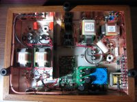
I ended up building this modified circuit. Leerily (in light of the above problems with an internal PS described in the thread), I began with a chassis containing the power supply. (It is a Chinese pre-made chassis, which I've used before, containing a 50K relay-based volume control and 4 input selectable RCA plugs, and a nice front display–––all controlled by an included remote.)
Surprisingly, the finished preamp is dead quiet, even though the PS is in the same chassis. The supplied chassis does feature a partition, and I did use one of Broskie's House-GND PCBs, so I don't know if that explains why I'm not needing to use an external PS box. But happy days with less work.
Beyond quiet, the preamp is very musical and certainly one of the better ones to which I've listened (I believe it bests the previous 6N6P that I built). I did come across some 6N6Ps which had their triodes closely matched; maybe that helps too.
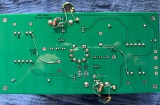
I've attached a PDF of the modified schematic, along with some photos of the back of the modified PCB (showing RC stages and FB resistors). The schematic contains simulated voltages along with actually measured voltages (my PS secondary is 300 VAC, giving a 322V B+, greater than quoted: 180-210V B+). Simulations show a 50% decrease in THD when increasing B+ from 180 to 320V (130V are dropped over the depletion mosfet; ~2W).
Please note: I do not have fancy bench-based, test equipment like Kevin (only a Fluke 87V and an oscilloscope), so I cannot verify the mods much beyond the simulations. Kevin may say that what I've done ruined what he designed, if so, my apologies. Perhaps further discussion can point out my mistakes.
A few months ago, I was reading this thread, as I was working on a different preamp using the 6N6P tube. After finishing that project, I was sufficiently intrigued to contact Kevin about getting some PCBs. He graciously emailed me Gerber files. It took me several weeks to get all the parts together (the LL1930s seemed to be in short supply).
While waiting for the parts, my usual practice is to simulate the circuit. I then usually play around with parts. I seem to understand that cascode CCS are the norm, but when simulating (if simulated THDs can be trusted), I found less 3rd order distortion (with slightly greater 2nd; better, no?), if only one device, not a cascode, was used. This freed up a little space on the board to add a decoupling RC stage (1Kohm + 68uF) to each channel's PS. Additional simulations showed some benefit by adding a 100K FB resistor from the negative output to the grid input. (The PS board was used as is; although I did add two UF4007 diodes as discussed in the PS PDF supplied by Kevin.) I also substituted a IXTY08N100D2 for the DN2540 device.
I ended up building this modified circuit. Leerily (in light of the above problems with an internal PS described in the thread), I began with a chassis containing the power supply. (It is a Chinese pre-made chassis, which I've used before, containing a 50K relay-based volume control and 4 input selectable RCA plugs, and a nice front display–––all controlled by an included remote.)
Surprisingly, the finished preamp is dead quiet, even though the PS is in the same chassis. The supplied chassis does feature a partition, and I did use one of Broskie's House-GND PCBs, so I don't know if that explains why I'm not needing to use an external PS box. But happy days with less work.
Beyond quiet, the preamp is very musical and certainly one of the better ones to which I've listened (I believe it bests the previous 6N6P that I built). I did come across some 6N6Ps which had their triodes closely matched; maybe that helps too.
I've attached a PDF of the modified schematic, along with some photos of the back of the modified PCB (showing RC stages and FB resistors). The schematic contains simulated voltages along with actually measured voltages (my PS secondary is 300 VAC, giving a 322V B+, greater than quoted: 180-210V B+). Simulations show a 50% decrease in THD when increasing B+ from 180 to 320V (130V are dropped over the depletion mosfet; ~2W).
Please note: I do not have fancy bench-based, test equipment like Kevin (only a Fluke 87V and an oscilloscope), so I cannot verify the mods much beyond the simulations. Kevin may say that what I've done ruined what he designed, if so, my apologies. Perhaps further discussion can point out my mistakes.
Attachments


I'm delighted you built it, even if you strayed pretty far from the original design. There was literally almost no interest in it then or since, so thank you for reaching out to me.
Note that if you want to apply feedback to the input you need to ground the secondary of the transformer to do it. Measurements indicated that negative feedback isn't required. (Note that this will also lower the input impedance substantially depending on gain required) Currently as connected it depends on the external GND connection for close the loop, and the position of the volume control determines both input impedance and overall gain.. I recommend removing the 100K resistor.
I've generally found the cascode to both measure and sound better than single mosfet based CCS, but in this case the RP of the 6N6P is pretty low and interactions with the mosfet are more benign. I observed improved performance with triodes like the 6S3P which has an rp typically of around 5K vs the 6N6P 1.2K or less.
The 6N6P is pretty linear. I enjoyed my line stage in the office system for a number of years, but the EML20B based line stage from my main system took its place recently as that system is all digital and the AD converter needed a solution with individually adjustable input gains as well as unbalanced to balanced conversion for the AD inputs.
Last edited:
I got to thinking that I should also supply the LTspice simulation file that I've been using for my above post. It is attached below, but a few comments are in order.
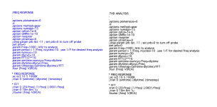
I've gotten into a habit of not using 'include' files, but rather pasting all the LTspice directives and models into the simulation file, so that the file is self-contained. Therefore, the 6N6P, the depletion IXTY08N100D2 mosfet, and the LEDs have their models at the bottom of the sheet (out of view; scroll down to see).
The other thing I started doing is to paste at the bottom, 2 sets of directives: one for Frequency Reponse and one for THD Analysis. I simply turn one off by changing it into a "Comment" rather than a "Directive", and vice versa when running the opposite analysis.
I've attached an image showing this setup: the FR is here a comment (so in blue), while the THD Analysis is a directive (so in black text). Switching the text definition back and forth seems to me to be a faster method than commenting-out statements. If any of this isn't clear, let me know.
***
Kevin, thanks for your comments. I posted this just before reading your post. I'm editing it now, to acknowledge your comments about the 100K FB resistor.
Attachments
Hi all,
Reviving this because I'm FINALLY building this project. En fin! I was lucky to score boards from Kevin early on but life (and low budgets and late HS and college aged kids and my age-addled brain) got in the way. I don't know if Kevin is watching this thread nor if others have the boards or Gerber's but I have a few questions. One is what value should I be using for C2 on the board? It's not on the schmatic as far as I can tell, but I seem to recall a value of 1,000uF. I assume it's a filter or decoupling cap on the incoming B+ on the board. Probably 350v or more, likely 450v.
Another is about the lack of a cap on the input. I don't see it discussed in this thread either. I think I know why Kevin didn't bother with it, but in my case I don't know if I can rely on no DC on the input. So if were to use a cap there, is it as simple as using the standard calculator for sizing the cap (e.g. inverse 2piFC)? Not sure yet how I'll implement it due to the fact that I'm wanting to add a transformer based balanced input for tape (which I assume wouldn't need a cap...).
Thanks, and I'm excited to get this going!
C2 is on the schematic, look again. 47uF/350V I believe I gave you a BOM at some point, plus the lead spacing and capacitor diameter are given on the schematic as well.
The input cap is not required in this application, there should be no DC present on the output of your sources - if there is that would be a bigger problem for the volume attenuator which might get noisy. ! I recommend you build it as designed. 😀
The pot should preferably be a 50K.
Mine uses a pair of LL1544 input transformers which do need to be loaded correctly. (The boards I have for you take care of that)
I assume you are talking about C5 in the filament supply which should be a 4700uF electrolytic capacitor. Look for one with the highest ripple current rating that will fit. I would recommend > 1.5A. (Cap will live a long and happy life)
These PDF are freshly generated from the original schematics and have all of the updates.
PSU
Note that you can use a choke in place of R1 (check above for more details) 5H 50R rated for about 50mA is a good starting point, and you can go higher as long as the DCR is not excessive - say 15 - 20Hz at 220R or less.) Best to put the PSU in a separate box - again see comments about circulating eddy currents in the case and their effect on the input transformers in particular, but not great on the outputs either.

Line Stage
In terms of buffered option vs direct you may prefer one over the other, only listening will tell. Do not switch jumpers while the power is on. Note that measured THD in mine is typically more than an order of magnitude lower than the value listed in the schematic at frequencies above 100Hz or so.

The input cap is not required in this application, there should be no DC present on the output of your sources - if there is that would be a bigger problem for the volume attenuator which might get noisy. ! I recommend you build it as designed. 😀
The pot should preferably be a 50K.
Mine uses a pair of LL1544 input transformers which do need to be loaded correctly. (The boards I have for you take care of that)
I assume you are talking about C5 in the filament supply which should be a 4700uF electrolytic capacitor. Look for one with the highest ripple current rating that will fit. I would recommend > 1.5A. (Cap will live a long and happy life)
These PDF are freshly generated from the original schematics and have all of the updates.
PSU
Note that you can use a choke in place of R1 (check above for more details) 5H 50R rated for about 50mA is a good starting point, and you can go higher as long as the DCR is not excessive - say 15 - 20Hz at 220R or less.) Best to put the PSU in a separate box - again see comments about circulating eddy currents in the case and their effect on the input transformers in particular, but not great on the outputs either.
Line Stage
In terms of buffered option vs direct you may prefer one over the other, only listening will tell. Do not switch jumpers while the power is on. Note that measured THD in mine is typically more than an order of magnitude lower than the value listed in the schematic at frequencies above 100Hz or so.
Attachments
Last edited:
Something to note is that I finished this project almost 3 years ago, and what I remember is not as much as one would hope, most of the useful information is in this thread. I have done a number of significant designs (mostly solid state) which are currently cluttering my mind - so before reaching out to grouchy old me, read the thread, if there is still an open question please post it here. I should also mention that I am still a hardware designer for a large consumer electronics company and have less bandwidth than I would like.
To Carl's question I would say that this is not at all popular which is a shame because it is a good performer, fairly inexpensive and not hard to put together. I imagine he will be the very last to put one together.
To Carl's question I would say that this is not at all popular which is a shame because it is a good performer, fairly inexpensive and not hard to put together. I imagine he will be the very last to put one together.
No, but would be happy to provide gerbers to anyone who agrees not to share or profit by them. As this is a year in the past likely the need has passed. Let me know if otherwise. JLCPCB is very cost effective and you are free to offer the surplus at cost in swap meet.I'm interested for sure!
As time permits I'm slowly working on a new amplifier and 26 preamp.
I have not used the 1930's yet but winter is coming and that's when I do most of my tinkering.
Will you be making any boards Kevin? I'd be interested.
- Home
- Amplifiers
- Tubes / Valves
- A Stereo 6N6P Hybrid Line stage w/Parafeed Output Transformer