Hi there,
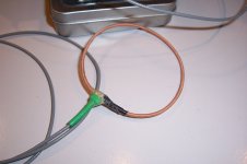
This Rogowski sensor is perfectly ordinary, except for one detail: the sensor coil is wound on the inner conductor of a RG316 coaxial cable.
This type of SHF cable has its inner conductor made of steel, because mechanical resistance is more important than ohmic resistance.
This means that the coil is no longer air-cored, as for a regular Rogowski: the core presents some magnetic permeability. In this case, it is low, because steel has poor magnetic properties, and occupies only a fraction of the core area: the equivalent apparent relative permeability here is ~3.
Why would anyone compromise the main virtue of Rogowski coil, linearity, by adding an imperfect, non-linear core?
Rogowski's are great, but they have a very low output, which is furthermore affected by a 6dB/octave slope, meaning their low-frequency output becomes quickly drowned in noise after the integrating conditioner.
Increasing the permeability improves matters, here by ~10dB: this doesn't look much, but it is far from negligible.
Of course, it also degrades the linearity, and adds a supplementary frequency-dependence: beyond ~20KHz, the steel begins to lose its properties, because of the eddy-currents and the skin effect in the silver plating. This requires additional equalization, but it's no big deal, and for a wide frequency range, equalization is required anyway.
The linearity aspect would become a problem at very high currents only: because the apparent permeability is so low, other effects are "diluted".
I estimated that non-linearities would become an issue for currents of the order of ~1kA.
This could be a problem for me, as I intend to reach peak currents of 1.5kA, but because it will be for a few µs only, it should not be a problem: the magnetic field will not have enough time to penetrate the steel core, and the coil will behave mostly like an air-core one
Attachments


Hello Elvee,
Very interesting ! I love your builds...
I will love to have a good current probe on my bench, like AM503/P6302 but even
used that cost much. Building a Rogowski probe is a good alternative...
Did you have made rise/fall time specs using fast current source ?
So, making the 1020 turns need to be very patient ! 🙂
Regards.
Frex
Thanks, the interest is mutual I also like your projects, and I will probably fall for your latest iteration of the low THD oscillatorHello Elvee,
Very interesting ! I love your builds...
Yes, the main drawback of the Rogowski is that it is AC only, but it's perfectly possible to learn to live with it.I will love to have a good current probe on my bench, like AM503/P6302 but even
used that cost much. Building a Rogowski probe is a good alternative...
A Rogowski is also flexible, both figuratively and literally: with my build, I can easily slip between the legs of a TO247, and it is possible to make it even slimmer, for a TO220 for example.
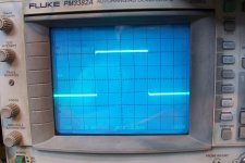
See the oscillogram below: about 100ns, but the current generator only has marginally better performances, which means it is actually somewhat better.Did you have made rise/fall time specs using fast current source ?
The bandwidth spans from 3Hz to 4MHz, which fits well with the rise time
It is a bit tedious, but if you are well organized, it takes less than an hourSo, making the 1020 turns need to be very patient ! 🙂
Attachments

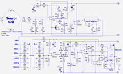
A few words of explanations/clarifications:
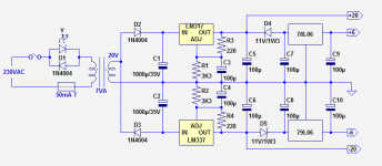
Some aspects of the circuit probably look odd, or even completely insane: the front-end supplies of +/-20V followed by the post-amplifier using +/-6V supplies for example.
This, and the rest is completely deliberate though.
I wanted to build a general purpose instrument, as sensitive as possible, with a good bandwidth, both for the low end of the spectrum and the high frequencies.
I normally do not need a current capability exceeding ~40A, like most of us, probably.
But I also intended to occasionally use the ammeter for special purposes: the study of discharge currents in capacitors. That requires a 1 to 2kA capacity.
I could have used two different probes, but this also means the complication of an input connector, plus the switching of all the equalization components.
Another option would have been to switch the main integrating capacitor for a lower sensitivity, but there again, all the equalizations have to be adapted.
In the end, I found simpler to use very high supplies for the front-end, combined with an integrator beginning to saturate at ~1500A, followed by a more "normal" post-amplifier.
On the first range, the output of the front-end is sent directly to the output, and can reach +/-15V.
The other ranges are limited to +/-4V, which is a little odd, but is not important for me, since I am not going to use (much) the interval between 40 and 1000A.
Circuit description:
The main integrator, U1 is an OP27: it is an ideal choice (although there are certainly more modern circuits performing marginally better) thanks to its high OL gain, low noise, low offset, low input current and good bandwidth.
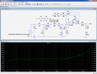
For a basic, textbook circuit, only R1, C3, C5, R5/6 would be required, but here, we want to cover 6 decades of frequency, and there is the additional complication of the magnetic core beginning to "fade" at 20kHz.
All the equalization components have been grossly estimated in simulation, and then hand-refined on the actual circuit.
In the sim file, R13, R14, C5 model (not very accurately) the behavior of the magnetic core. It is simpler than incorporating it in the coil itself, and the result is equivalent (note that this circuit is not up to date).
The resulting square-wave response is decent, but not perfect, as can be seen in the oscillogram.
At the adjustment stage, I could obtain a perfect response, but with odd-value components.
I replaced them with with standard E12/E24 ones, because the response is somewhat affected by the position of the current to be measured inside the loop.
This shouldn't be so, of course, but the coil has a number of distributed parameters, and the effect is different depending where the measured current is situated wrt. to the start and finish of the winding.
This could be avoided with a smaller coil, but the sensitivity would also be reduced, which is why I accepted this tradeoff (and wasn't maniac about the equalization values)
The time-constant of C6*R7 looks unreasonable, but it works, because the initial offset of the opamp is minuscule, and even if the leakage resistance of C6 is significant, it doesn't prevent the circuit from zeroing, eventually.
After the calibration trimmer, the signal can optionally be low-pass filtered, to remove HF hash when it is not needed. I have chosen 300kHz, but other frequencies would be possible.
Then, follows a high pass filter: because the low-frequency gain is pushed to extreme values by the integrator, the noise becomes significant, making the base-line shaky at high sensitivities: when the lowest frequencies are not needed, they can be removed, making the display much quieter.
I have chosen a number of steps, again more or less arbitrarily.
A diode clipper is inserted between the filter and the rest of the circuit, to avoid damaging the low-voltage/high-speed opamps.
Initially, they were both OPA620, but the first one didn't like feeding the output selector switch open-circuit, and stubbornly oscillated at 250~300MHz, whatever I did.
I never managed to tame it completely, even by fractionating the output resistor to "break" stubs, and in the the end I tried the CLC420, which is equivalent on paper, but didn't show any sign of instability.
Some aspects of the circuit probably look odd, or even completely insane: the front-end supplies of +/-20V followed by the post-amplifier using +/-6V supplies for example.
This, and the rest is completely deliberate though.
I wanted to build a general purpose instrument, as sensitive as possible, with a good bandwidth, both for the low end of the spectrum and the high frequencies.
I normally do not need a current capability exceeding ~40A, like most of us, probably.
But I also intended to occasionally use the ammeter for special purposes: the study of discharge currents in capacitors. That requires a 1 to 2kA capacity.
I could have used two different probes, but this also means the complication of an input connector, plus the switching of all the equalization components.
Another option would have been to switch the main integrating capacitor for a lower sensitivity, but there again, all the equalizations have to be adapted.
In the end, I found simpler to use very high supplies for the front-end, combined with an integrator beginning to saturate at ~1500A, followed by a more "normal" post-amplifier.
On the first range, the output of the front-end is sent directly to the output, and can reach +/-15V.
The other ranges are limited to +/-4V, which is a little odd, but is not important for me, since I am not going to use (much) the interval between 40 and 1000A.
Circuit description:
The main integrator, U1 is an OP27: it is an ideal choice (although there are certainly more modern circuits performing marginally better) thanks to its high OL gain, low noise, low offset, low input current and good bandwidth.
For a basic, textbook circuit, only R1, C3, C5, R5/6 would be required, but here, we want to cover 6 decades of frequency, and there is the additional complication of the magnetic core beginning to "fade" at 20kHz.
All the equalization components have been grossly estimated in simulation, and then hand-refined on the actual circuit.
In the sim file, R13, R14, C5 model (not very accurately) the behavior of the magnetic core. It is simpler than incorporating it in the coil itself, and the result is equivalent (note that this circuit is not up to date).
The resulting square-wave response is decent, but not perfect, as can be seen in the oscillogram.
At the adjustment stage, I could obtain a perfect response, but with odd-value components.
I replaced them with with standard E12/E24 ones, because the response is somewhat affected by the position of the current to be measured inside the loop.
This shouldn't be so, of course, but the coil has a number of distributed parameters, and the effect is different depending where the measured current is situated wrt. to the start and finish of the winding.
This could be avoided with a smaller coil, but the sensitivity would also be reduced, which is why I accepted this tradeoff (and wasn't maniac about the equalization values)
The time-constant of C6*R7 looks unreasonable, but it works, because the initial offset of the opamp is minuscule, and even if the leakage resistance of C6 is significant, it doesn't prevent the circuit from zeroing, eventually.
After the calibration trimmer, the signal can optionally be low-pass filtered, to remove HF hash when it is not needed. I have chosen 300kHz, but other frequencies would be possible.
Then, follows a high pass filter: because the low-frequency gain is pushed to extreme values by the integrator, the noise becomes significant, making the base-line shaky at high sensitivities: when the lowest frequencies are not needed, they can be removed, making the display much quieter.
I have chosen a number of steps, again more or less arbitrarily.
A diode clipper is inserted between the filter and the rest of the circuit, to avoid damaging the low-voltage/high-speed opamps.
Initially, they were both OPA620, but the first one didn't like feeding the output selector switch open-circuit, and stubbornly oscillated at 250~300MHz, whatever I did.
I never managed to tame it completely, even by fractionating the output resistor to "break" stubs, and in the the end I tried the CLC420, which is equivalent on paper, but didn't show any sign of instability.
Attachments
Thanks, I like to share useful, interesting or unusual bits like this one.Interesting work, good job done, thumbs up!
Construction notes:
I wound the sensor coil by holding the core cable (center from RG316) taught between two vices, one stationary and the other portable.
I stored the wire to be wound on a shuttle, and every few turns, I packed them by hand, to get a nice, uniform winding, without voids or irregularities.
I used a silk+enamel insulated wire, for a good insulation, and benefit from a cushioning effect to improve flexibility.
I dipped the finished winding in several layers of flexible urethane and silicone, for protection against mechanical abuse and contamination.
The end plugs are made with heatshrink tubing.
Many other probes types can be built, but all the components of the integrator will need to be adapted.
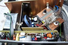
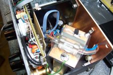
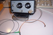
The integrator is a critical part, and in addition to a good opamp, it needs to be well shielded, especially from magnetic fields.
In my build, it is encased in the soft steel box, far side from the transformer.
The box has double walls, and an additional screen separates it from the transformer.
The transformer itself is optimally oriented to minimize the effect of stray fields, but even with these rather drastic precautions, some low level 50Hz hum is still detectable, about the same level as the rest of the noise.
It is not really problematic, but for total quietness, the best solution is to split the supply from the rest and use an umbilical.
I may add a connector for the +/-20V at a later date, to be able to feed the circuit from an external supply in case I need super-quietness.
The rest is pretty standard stuff, and the supply is ordinary too.
The post-amp opamps must have a GBW commensurate with the 20dB gain and the desired bandwidth.
Attachments
Hi Elvee, Most impressed as I am looking at winding a rogowski coil too. I have the text book basics (but I hated magnetics in college) and understand that sensitivity is proportional to turns and cross sectional area. A couple of questions however....
1/ does the coil need to be single layer?
2/ If multiple layer, does each layer need to start at the same position?
3/ Does this imply more than one wire down the centre?
4/ If the coil is long can it be wound several times around the primary?
5/ Alternatively, would several smaller coils in parallel multiply the sensitivity?
I am seeking an overcurrent sensor with zero insertion loss for my amp speaker protection.
Thanks
John
No, it can be multilayer, and with two layers (or any even number), you do not need the center return conductor, you just reverse the winding when the end of the first layer is reachedHi Elvee, Most impressed as I am looking at winding a rogowski coil too. I have the text book basics (but I hated magnetics in college) and understand that sensitivity is proportional to turns and cross sectional area. A couple of questions however....
1/ does the coil need to be single layer?
The whole winding has to be completely homogeneous, and for all aspects2/ If multiple layer, does each layer need to start at the same position?
No, see above3/ Does this imply more than one wire down the centre?
In principle, yes, but it could be the source of a topological problem: both end of the winding must face each other, so that the loop is closed4/ If the coil is long can it be wound several times around the primary?
Yes, it is done, except they are in series, not parallel5/ Alternatively, would several smaller coils in parallel multiply the sensitivity?
I would strongly advise against a rogowski for such an application: speaker problems occur mainly at low frequencies or DC, where the rogowski has a minimal or zero sensitivity.I am seeking an overcurrent sensor with zero insertion loss for my amp speaker protection.
A Hall-based sensor does not have these issues, and also has zero insertion loss: have a look at this type of component for example:
http://www.lem.com/docs/products/hxs_10-np_sp3.pdf
Thanks Elvee, you have saved me many hours of coil winding pain and thanks for the LEM data - looks like the way to go.
Many years ago I was designing arc extinguishing means for residential circuit breakers during overload using the rapid expansion of super heated air to "puff" the arc out. Wish I had found Rogowski coils back then for the validating measurements.
Many years ago I was designing arc extinguishing means for residential circuit breakers during overload using the rapid expansion of super heated air to "puff" the arc out. Wish I had found Rogowski coils back then for the validating measurements.
hi @Elvee .
Do you think it is possible to use a Rogowski as a current sensor (instead of a very normal resistor in series with the loudspeaker) to create a feedback on the power amplifier and thus obtain motional feedback or current driving?.
I don't know if it's possible to get a decent output at low audio frequencies and I don't know if it can go up to 20KHz.
Possible: yes. Advantageous, I don't think so: you need serious conditioning to equalize the FR and if you don't need the contact-less feature, a simple resistor looks much simpler.
Either solution can be used for current feedback; motion feedback relying just on current looks more haphazard: it will require serious signal-processing
Either solution can be used for current feedback; motion feedback relying just on current looks more haphazard: it will require serious signal-processing
FR stands for frequency response ?.
in addition to not having direct contact there is also an absence of ohmic resistivity. a 0.1 ohm series resistor is small but with high currents it generates some noise.
If you were the one to build it how would you do it? .
in addition to not having direct contact there is also an absence of ohmic resistivity. a 0.1 ohm series resistor is small but with high currents it generates some noise.
If you were the one to build it how would you do it? .
Yes, Frequency Response. At low frequencies, where feedback makes sense, a Rogowski will be much noisier than a small resistor, because the amplification is huge. In addition, for a closed loop system, you will need to tackle the complicated phase response of the sensor and its equalizing network.
I would rather use a zero-flux current transformer: a ferrite toroid with a good number of turns loaded by an active circuit acting as a virtual short.
The sensitivity and SNR will be much better, and it is also a zero ohm solution
I would rather use a zero-flux current transformer: a ferrite toroid with a good number of turns loaded by an active circuit acting as a virtual short.
The sensitivity and SNR will be much better, and it is also a zero ohm solution
Here is an example of zero-flux transformer, albeit an extremely imperfect one:
https://www.diyaudio.com/community/...transformer-based-circuit.356221/post-6247241
A regularly wound toroid would be almost perfect in comparison, and if it is aimed at audio rather than metrology, it should be close to ideal.
Note that in any case, the inductive sensor will introduce a pole in the response, and if other similar poles created by coupling caps for example are present, instability might occur (I am not even taking into account the electromechanical properties of the driver)
thanks and congratulations for your work.
How did you solve the stray magnetic fields problem?.
if the nucleus has a high permeability such as mu-metal for example, it could collect what comes to it from a nearby electrical network which in my case is 50 Hz and this frequency falls within the audio range.
How did you solve the stray magnetic fields problem?.
if the nucleus has a high permeability such as mu-metal for example, it could collect what comes to it from a nearby electrical network which in my case is 50 Hz and this frequency falls within the audio range.
- Home
- Design & Build
- Equipment & Tools
- A slightly unusual Rogowski sensor