 This thread split off from the Blowtorch part II thread. April 20th 2017
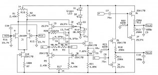
I promised Patrick that I would post the final schematic of this circuit so here it is. I have a lot of JFET's in bags here and there but I didn't get inspired until I realized how simple the common-mode feedback would be to do with nothing but FET's. There is nothing that special here, a simple undegenerated diff-pair, folded cascode, and buffers. J11 provides common-mode feedback and for a differential signal has no "work" to do but keep the common-mode DC level around 0.0V, so I don't even consider it in the signal path. So we have a purely current driven RIAA network with all the time constants between two nodes. The AC coupling in the output is optional, I don't like servos so what.
Almost everyone I show this to starts adding more supplies, extra cascodes, current sources, etc. that's not the point. Bob Cordell published a phono pre-amp in Linear Audio and I started looking at this as removing things from it until it stops working (Muntzing).
The output buffers are a little side experiment. I chose the FET's in a way contrary to just about what everyone else does. I did NOT match the Idss's, instead I sorted them such that a single standard value of source resistor would set the operating current at the same value. I picked 5mA and used a homemade curve tracing jig to sort 25 each N and P FET's. So now when they are connected together the input to output offset is 0, no trims. It turns out that this had less un-trimmed distortion (in sim) than selecting equal Idss's and trimming for just offset (story for another day). Worked fine when stuffed all four were < 5mV. I picked some reasonable matches for the rest of the pairs. I had to snub the output of the buffers with 680pF.
Notes on the amplifier:
I chose the LSK489 FET pair (thanks Paul Norton and Linear Systems for their support of the DIY community) because it had higher Vp and lower transconductance (gm) which gives a wider range of linear input and keeps the RIAA network's impedance level from getting too low. Bob used the LS844 which has the same gm at 1mA and chose 20dB midband gain but his load resistor value does not reflect that(Bob ???). I chose 26dB midband gain and used the 3mS gm at 2mA from Bob's app note which should be the correct value. R7 is chosen for around 1.0ma per side of quiescent current, that and a goal of 46dB of DC gain gives you a target for R19 and R3. At 2.2mS gm for the FET at 1mA two 90.9K resistors were chosen and the rest of the RIAA values fell from that. The caps were all chosen from a large NOS stash of TRW 1-3% polystyrene hence 9.375n was actually an exact available value. The resistors are all 1% Dales with R20 two standard values in series, while C4 was two caps in parallel.
Since all LSK489's have nearly the same gm at 1mA R7 was a trim on the second channel for gain, and it was easy to get nearly .1dB match. The lowish midband gain means a low noise line stage is necessary if you want the SNR limited by the input FET noise alone over the entire audio band, if you take A weighting into account I'm not sure this matters much at all. For first listening I will use a low noise in-amp at a gain of 14dB to bring up the midband gain to a more standard 40dB and give me a single ended output since as yet I don't have a differential input system.
R18 and R17 are redundant offset trims, the idea was that by skewing one and bringing the offset back with the other one might be able to null the residual second harmonic. The distortion was so low I would not include both again.
The three green LED's set the current in the folded cascode to around 1.75mA this is not super critical it just wants to be enough. R4 could be a trim, it sets the common-mode voltage but I just computed the value and put it in.
First light:
Distortion at 1K with .025Vrms in, ~-87dB (.0045%) Nothing much other than 2nds and 3rds (almost the same as Bob's). The noise was input FET limited at 3-4nV/rt-Hz (out to the last octave or so) fine for MM/MI which was the goal. MC would require some rework.
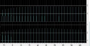
RIAA accuracy is pretty good (the drop at 20k is Windows brick-walling my soundcard at 22.05k in the background) and the low rolloff is half due to my added high pass at the output. Mostly +-.1db out of the box. Picture is both channels (offset is random and does not indicate the gain mismatch). The RIAA response used a 1/3 octave multi-tone (30 tones) signal pre-emphasized at the same .025mV rms in which will have a crest factor more like recorded music. No IM noise floor was observed.
This is a work in progress, the recent availability of complimentary pairs of FET's from Linear Systems means that it may be possible to realize this entire signal path with LSK489's and LSK689's. I know this is JC's thread but it is the lounge after all. Comments like, "We did this fully complementary 40yr. ago", etc. are inevitable, I've learned there is no point in asking them not to come flying.
EDIT - The supplies are +-15V and the bypassing is left up to the builders personal practice.
Attachments
Last edited:

Thanks Scott for the schematic and detailed explanations.
Playtime begins tonight ...
Now, where did I put those TRW caps ...
😀
mlloyd1
Playtime begins tonight ...
Now, where did I put those TRW caps ...
😀
mlloyd1
I promised Patrick that I would post the final schematic of this circuit so here it is.
Scott -- how does it do on overload? I'm not in the mode of a RIAA, but the CM feedback mechanism and the overarching elegance of the circuit makes for a fun idea to play with (to this amateur).
And of course, thanks for the circuit, and, IMO more importantly, the explanation.
And of course, thanks for the circuit, and, IMO more importantly, the explanation.
It behaves like Bob's for the most part, I'll look at clipping of the actual build since I have relied on sims for that. I expect very soft compressive behavior especially for tick and pops.
Thanks Scott for a voice of reason and rationality - had a bad day with the trolls on diyaudio..😡
Jan
Jan
Not bad actually, better than you would think. Put this on a 5V battery and a Silentswitcher, time for some DBT if you can stand it.
There was some 100MHz fur probably gate stoppers would also get rid of it but that would involve cutting and soldering and I already killed one 75n poly cap by just brushing it with a hot iron.
Scott -- how does it do on overload?
As good as I expected, more than 25Vp-p at clipping and at 20Hz there is a little droop after clipping from the common mode loop or the coupling cap, nothing pathological. Your woofers would be long gone before this. THD at 250mV rms in is still <0.5% and still no 7th's 😀. FET's just can't make high order harmonics.
still no 7th's 😀
Pity, sometimes a minor seventh really helps a chord out. 🙂
Nice to hear it's well-behaved into overload conditions. Or, well, see.
What is the CMR vs freq and the +/- PSRR vs freq?
THx-RNMarsh
CMRR was -86dB at 1kHz, pretty much follows the RIAA curve so I would say fairly constant with frequency. I was scared for a minute because I am using two channels of a sound card to make a true differential input and when I set the phase to 0 the CMRR didn't look so good. The DAC's turn out to have 0.5% gain mismatch, had to short the inputs and use one DAC.
I removed the bypassing and nothing oscillates so I was thinking I would try to measure PSRR by putting an old output transformer backwards to inject some AC in series with the supply with the 4 Ohm tap. Anyone try this before?
Congratulations Scott, you finally found the audio usefulness of using all fet designs! Can't make 7th harmonic? Good!
I removed the bypassing and nothing oscillates so I was thinking I would try to measure PSRR by putting an old output transformer backwards to inject some AC in series with the supply with the 4 Ohm tap. Anyone try this before?
I have made a box/little board with 2 BB/TI BUF634( 5pin-TO220) for Vcc/vee + noise / sweeper input but never really used it at all. Seriously, I need more time.
And I insist that the raw supplies are reasonably clean; if someone needs 110 dB PSSR
that means that he already has all the dirt on his board.
cheers, Gerhard
Attachments
Last edited:
That's what we do with VI's in the testers, looking to avoid building something I will never use again. I had a tech once that floated a whole Kronhite but made a miss-connection that let lots of magic smoke out.
Last edited:
Hey, I once worked for Verigy (ex HP) and I had a medium sized mixed signal tester just for my work; I was the only user, including somewhere an AP 2732(?, like an early eprom) which was a major PITA in the system and was floated. They needed someone who understood Unix/Linux drivers as well as TDR ... For me, it was too software-centric in the long run. Especially if they had the newest 50 GHz VNAs in the next cubicle and I had to ignore them. Yes, more than one or two.
Last edited:
Almost missed the post of Scott's RIAA.
Thanks for sharing with us, and look forward to a high(er) gain version before too long.
😉
Best regards,
Patrick
Thanks for sharing with us, and look forward to a high(er) gain version before too long.
😉
Best regards,
Patrick
Using the same philosophy you might need 6DJ8's at the input rather than JFET's. The gain structure for open-loop amplifiers is a difficult trade-off unless you punt the THD and say -60db is fine or something like that.
OTOH I have a third board and lots of FET's from Paul Norton there might be a sweet spot with an LSK389 and more bias current to get the 14dB of gain back.
OTOH I have a third board and lots of FET's from Paul Norton there might be a sweet spot with an LSK389 and more bias current to get the 14dB of gain back.
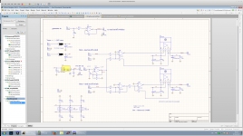
Remember the spice files I sent you a while ago for the version with 300x gain at 1kHz ?
In spice at least, THD is quite decent at 2Vrms out, using 4x 2SK372 at the input.
Maybe you would have another look at see if I have done something really silly......
Patrick
In spice at least, THD is quite decent at 2Vrms out, using 4x 2SK372 at the input.
Maybe you would have another look at see if I have done something really silly......
Patrick
- Home
- Source & Line
- Analogue Source
- A simplified universal differential or single ended phono preamp