It is a simple follower without any voltage gain.I found this intresting dead simple headphone amp schematic, i also simulated it and it can do up to 2V rms.
View attachment 1425162
Most cases it can do well without the gain.
It is only headphones with higher impedance that needs voltage gain.
This one can be good and simple preamp too, must try it, because I have all parts available. Any suggestions about J113's Idss value or it doesn't matter?Gain is like R1/R2+1
Most cases there is not any need for an input capacitor.
R5 does not need to be 1M. It could even be 100k.
Thats why i wanted to use your preamp with it.It is a simple follower without any voltage gain.
Most cases it can do well without the gain.
It is only headphones with higher impedance that needs voltage gain.
if i run it at low enough voltage i could get a great iem/inear amplifier i think 5V is enough to get all of the voltage swing from any portable headphone dongleIt is a simple follower without any voltage gain.
Most cases it can do well without the gain.
It is only headphones with higher impedance that needs voltage gain.
also what if i could replace the input bjt with a jfet to get rid of the input capacitor?It is a simple follower without any voltage gain.
Most cases it can do well without the gain.
It is only headphones with higher impedance that needs voltage gain.
Some measured J113 for 'lineup' preamp. Message #210. They specify in datasheet only min Idss=2.0mA. Seems to be four fet's near 12mA.

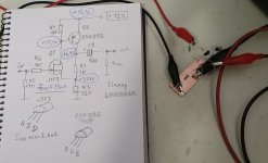
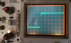
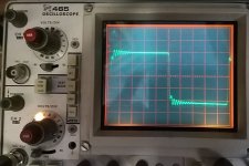
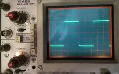
When using only sinewave everything works well, but 10kHz squrarewave shows some ringing and 100kHz is even worse. This amp needs some compensation cap inside feedback loop, maybe over pnp transistors C-B junction.
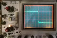
Edit: one 20pF comp cap is enough to correct this , last picture shows 10kHz sq wave with comp cap. Simulations are fancy, but in most cases they don't show all.
Edit: one 20pF comp cap is enough to correct this , last picture shows 10kHz sq wave with comp cap. Simulations are fancy, but in most cases they don't show all.
Attachments
Last edited:

I now will add this amplifier into my SPICE.its this one:
View attachment 1423157
And do some run - let's see if there can be any improvements.
understandable@No ideas
I have only a small room and a kitchen.
In my rooom I have no space left for electronics.
It is sad - I used to do audio work where I lived before.
Member
Joined 2009
Paid Member
I like this project, reminds me of my own, because of the kinda Sziklai feel about the circuit.
There's something v satisfying in building simple topologies although there are plenty of details that need attention to make it an interesting project. I haven't used my amp for a few years, your thread has brought back some good memories of it.
Grasshopper - headphone amp for Grado
Headphone amplifier for Grado.
I just took delivery of some headphones. They have a low impedance of 32R which doesn't vary too wildly with frequency. It seems that they don't use a lot of voltage, line-level is enough. They will sit in their box until I have made something with my own hands to drive them.
I've never heard, designed or made a headphone amplifier before; time for Grasshopper to learn....
- Bigun
- Replies: 41
- Forum: Headphone Systems
There's something v satisfying in building simple topologies although there are plenty of details that need attention to make it an interesting project. I haven't used my amp for a few years, your thread has brought back some good memories of it.

Member
Joined 2009
Paid Member
Maybe something like this?@No ideas
I have only a small room and a kitchen.
In my rooom I have no space left for electronics.
It is sad - I used to do audio work where I lived before.
I will try this.could you try to swap the constant current source with a bootstrap circuit?
Wait some hour
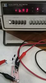
It look like the CCS is like 1.2mA. This is very little ...
That looks cool
- Home
- Amplifiers
- Solid State
- A simple discrete one-watt amplifier