SCP-1A output impedance with no load
Hi aszoke,
I have been simulating the output impedance of SCP-1A stage.
The input of stage was grounded and I used V1 as voltage source series connected with R16 changed to 400 ohms instead 40 ohms and series connected to L1 ( changed the value to almost zero for no effect in results ) connected to output stage. The output was disconnected from second stage.
See reults in attached files:
eD
Attachments
Last edited:
SCP-1A output impedance with loads
Now, the graphs show the results of output impedance with load.
On the first, is the results of just 750 ohms as load.
On the second, is the results of 750 ohm // 100nF as original circuit for RIAA use.
eD
Now, the graphs show the results of output impedance with load.
On the first, is the results of just 750 ohms as load.
On the second, is the results of 750 ohm // 100nF as original circuit for RIAA use.
eD
Attachments
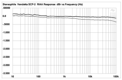
This is the measured frequency response of a Vendetta. It is sufficient
proof that Mr.Curl knows exactly what he needs to know about the input
stage's output impedance.
proof that Mr.Curl knows exactly what he needs to know about the input
stage's output impedance.
Inverting or Non-Inverting ???
Hi John,
In the Stereophile magazine Vendetta´s review, John Atkinson says that the unit he tested is non-inverting but the "our" schematic is inverting type.
Was Vendetta inverting or non-inverting type ? Or there was two types ?
Thanks
eD
Hi John,
In the Stereophile magazine Vendetta´s review, John Atkinson says that the unit he tested is non-inverting but the "our" schematic is inverting type.
Was Vendetta inverting or non-inverting type ? Or there was two types ?
Thanks
eD
Stereophile Inverse Riaa for Vendetta
Hi Werner,
My simulated RIAA response shows roll-off before 100kHz with that inverse Riaa network. I believe there is a slight diference between this and that Stereophile used.
Do you know what IRIAA they used ?
Thanks
eD
This is the measured frequency response of a Vendetta. It is sufficient
proof that Mr.Curl knows exactly what he needs to know about the input
stage's output impedance.
Hi Werner,
My simulated RIAA response shows roll-off before 100kHz with that inverse Riaa network. I believe there is a slight diference between this and that Stereophile used.
Do you know what IRIAA they used ?
Thanks
eD
that inverse Riaa network
Could be you are using an inverse network with an extra 3.18μS "Neumann" time constant a la Hagermann ?
Martin,
Please accredit the "Neumann" TC to it's correct presenter - myself. Jim Hagemenan got it from me.
It was first published in my 1995 TubePreamp CookBook, along with the full story. And had been in use in our phono preamps since it's first development around 1975!
Regards, Allen (Vacuum State)
Please accredit the "Neumann" TC to it's correct presenter - myself. Jim Hagemenan got it from me.
It was first published in my 1995 TubePreamp CookBook, along with the full story. And had been in use in our phono preamps since it's first development around 1975!
Regards, Allen (Vacuum State)
Could be you are using an inverse network with an extra 3.18μS "Neumann" time constant a la Hagermann ?
Yes!
Is it correct inverse network?
I want to know why my simulation is different from Stereophile´s measurement.
Do you know ?
eD
Last edited:
Sorry Allen,
I am aware that you presented the Neumann constant - but I was actually referring to the specific inverse filter circuit with the component values as published by Jim Hagermann - I saw this inverse circuit used in simulations, hence my assumption that Eddelarue was using this also ...
I am aware that you presented the Neumann constant - but I was actually referring to the specific inverse filter circuit with the component values as published by Jim Hagermann - I saw this inverse circuit used in simulations, hence my assumption that Eddelarue was using this also ...
Last edited:
IRIAA from Lipshitz
Ok folks,
I saw where the diference was.
I used the RIAA network from Lipshitz on my simulations and the result was very similar to the Stereophile´s graph.
eD
Ok folks,
I saw where the diference was.
I used the RIAA network from Lipshitz on my simulations and the result was very similar to the Stereophile´s graph.
eD
Last edited:
I use the Lipshitz-Jung passive reverse RIAA to make my adjustments. I have used it since 1980 or so. I have found nothing better, nor do I believe that significant changes to the RIAA, sometimes made by others, is very useful. This is because of the different characteristics of disc cutters, such as Neuman and Ortofon, as well as the ultrasonic behavior of most MC phono cartridges, which I have measured, myself.
Thanks John!
You have a large experience in RIAA issues and I believe that your choice is the better.
From now and go on, I will use the same Inverse RIAA because when I post something about it in this thread, we are talking the same language.
regards
eD
You have a large experience in RIAA issues and I believe that your choice is the better.
From now and go on, I will use the same Inverse RIAA because when I post something about it in this thread, we are talking the same language.
regards
eD
For simulations I found that using a laplace transform works very well and removes any tolerance errors or other stuff. I think the implementation came from the spice thread here.
I would rather use an error free source that constantly battle a mix of errors and conflicting interpretations. The extra corner(s) in the RIAA curve may or may not be there in the source, depending on what a disc was cut with (not to mention the rest of the chain,) when it was cut and whether they would be at the same frequencies with 1/2 speed cutting. It all gets too ill-defined as these things creep in. I prefer to approach the problem more like a tape chain starting from a well controlled standard.
I would rather use an error free source that constantly battle a mix of errors and conflicting interpretations. The extra corner(s) in the RIAA curve may or may not be there in the source, depending on what a disc was cut with (not to mention the rest of the chain,) when it was cut and whether they would be at the same frequencies with 1/2 speed cutting. It all gets too ill-defined as these things creep in. I prefer to approach the problem more like a tape chain starting from a well controlled standard.
Thanks eD. The simulations were very interesting for me. Which program do you use?Hi aszoke,
I have been simulating the output impedance of SCP-1A stage.
The input of stage was grounded and I used V1 as voltage source series connected with R16 changed to 400 ohms instead 40 ohms and series connected to L1 ( changed the value to almost zero for no effect in results ) connected to output stage. The output was disconnected from second stage.
See reults in attached files:
eD
Thanks eD. The simulations were very interesting for me. Which program do you use?
OrCad Capture with pspice. The same we can get from Microsim8.
eD
Frequency response
Sorry John,
still comparing to Stereophile´s graph I had posted two more graphs from simulation.
It seems that the second presents some difference to stereophile´s response.
Is that slow roll-off at high frequency when comparing to response of Stereophile important ?? It causes audible difference?
regards
eD
Attachments
I think you are worrying too much about small frequency response differences. I use the Lipshitz-Jung passive pre-emphasis module to give me flat response within .1 dB, if possible, over the entire audio bandwidth. I prefer to leave the attenuation in the ultrasonic region to keep dropping after 50KHz in order to reduce the mass resonance at approximately 50KHz that many cartridges have, and to reduce ultrasonic artifacts generated by stylus mistracking.
- Home
- Source & Line
- Analogue Source
- A real Vendetta?