Hi all,
Background:
I am building a WAW system. I have completed the 8" woofer bass reflex part and am interested in a mid-transmission line for my full range units. I currently have a pair of MA Pluvia 7s, MA Alpair 5.2s and a pair of Fostex FE103ENs. They will sit in a space above the woofer and will be interchangeable (modular). The space available is 30cm wide (overall width of speaker 32.4cm), height 24cm (overall height of speaker 86cm) and a depth of 39cm. Crossover will be about 350Hz (300-400 range), 1st or 2nd order passive. My Pluvia 7s and Fostex are currently in temporary boxes and I have been experimenting with the xovers.
Question:
I am contemplating a simple square or rectangular open backed tube of 39cm depth minus the thickness of the baffle, lined and stuffed. Is there any advantage of going tapered, bearing in mind that I will be making several of these?
Last edited:
Depends on the design specifics; there isn't a fixed answer to that per se. However, assuming volume swamps Vas, or at least is sufficient not to have excess gain peaking at Fp, then tapering a sealed mid-TL is worth the effort inasmuch as you can usually get away with a smaller stuffing density & have fewer issues with lateral eigenmodes. Since the pipe is stuffed anyway, and in most mid-TLs these are likely to be at a releatively high (easily suppressed shorter wavelengths) frequency this particular aspect is rarely a major issue, but for the sake of a little extra effort, might as well do everything you can that helps. This can apply particularly if the internal walls are in relatively close proximity to the driver, which is generally best avoided, but not always feasible.
Exactly the same remarks apply. It just happens to be tuned lower, and ultimately will unload < Fp, but assuming you've got sufficient stuffing in there and an appropriate high pass, not so you'd notice / have any functional impact in this (or most) applications.
I am building a WAW system.
What is your thinking behind using a TL under these circumstances?
I imagine the same as most others doing so: to flatten the impedance at the bottom end of its passband. Many such systems use low order passive filters at a relatively low frequency, so the use of an impedance-flattening mid-TL obviates the need for a series LCR notch, which can be rather expensive given the component values. Caps are rarely the issue, inductors, on the other hand, are, unless you wind your own, which not everybody is in a position to be able to do. Active is an alternative which also addresses that particular issue of course, but not everybody is in a position to be able to use active systems, nor interested in doing so either. Many also find that mid-TLs are a rather effective way of eliminating internal reflections etc. and maintaining a decently consistent air-load for the driver. Not the only one, naturally, but done well, a valid and effective approach.
Last edited:
It’s certainly an approach that has worked well in at least 1/2 dozen WAW designs I’d built from Planet10 designs over the past 10 years or so- using FF85K and WK, as well as various iterations of the Alpair 7. Haven’t built anything new in over a year and half, and the recent slew of new MA drivers almost has me jonesing.
Flattening impedance and reducing internal reflections are my goals. I take it then that stuffing sufficiently is important and that little or no stuffing would make it like an open baffle which would have a resonant peak similar to its free air resonance.
No, it would be an undamped QW resonator with the characteristics appropriate to the specific line geometry used.
So yes: for a mid-TL damping (stuffing or lagging) is extremely important. Some like a progressive damping density (increasing density as you move toward the terminus), others prefer it to be uniform. Technically it doesn't make much difference in & of itself in the majority of such applications; I prefer the former for short pipes of this type simply because it reduces the possibility of the air mass-loading the moving components of the driver and preventing it from oscillating / resonating as designed, which can occur with high stuffing densities in close proximity.
So yes: for a mid-TL damping (stuffing or lagging) is extremely important. Some like a progressive damping density (increasing density as you move toward the terminus), others prefer it to be uniform. Technically it doesn't make much difference in & of itself in the majority of such applications; I prefer the former for short pipes of this type simply because it reduces the possibility of the air mass-loading the moving components of the driver and preventing it from oscillating / resonating as designed, which can occur with high stuffing densities in close proximity.
Last edited:
A short conical TL sealed with stuffing progressively dense towards vertex works great as an acoustic black hole. I tried vented and it doesn’t work better so easier to just go sealed. I made a 3 or 5 sided pyramid for a “Dagger”. Alternatively, a 9in tall sports soccer pylon works well too.
The Dagger has property of essentially zero back chamber coloration. It measures same as an OB in frequency response. For a FAST/WAW application frequency is no lower than 250Hz.
10F/8424 & RS225-8 FAST / WAW Ref Monitor
10F/8424 & RS225-8 FAST / WAW Ref Monitor
The Dagger has property of essentially zero back chamber coloration. It measures same as an OB in frequency response. For a FAST/WAW application frequency is no lower than 250Hz.
10F/8424 & RS225-8 FAST / WAW Ref Monitor
10F/8424 & RS225-8 FAST / WAW Ref Monitor
True, but damping impedance is a primary goal here, so how much does it flatten impedance?
IME it takes a stuffed Fs/Qts' tuned TL with a 4 - 10x Vas [Vb] depending on how large Vas is.
Qts' = Qts + any added series resistance [Rs]: HiFi Loudspeaker Design
GM
IME it takes a stuffed Fs/Qts' tuned TL with a 4 - 10x Vas [Vb] depending on how large Vas is.
Qts' = Qts + any added series resistance [Rs]: HiFi Loudspeaker Design
GM
The attachment is an example of Planet10s Tysen speaker. It was a Fostex FF85KeN that had an Fs of about 130Hz and presumably a small Vas. The Pluvia 7 has an Fs of 67Hz and a Vas of 5.54 litres. Does this mean that the line would need to be considerably bigger in length and volume to get a similar flattening of the impedance?
Attachments
Yes. They have a similar effective Q, but having a higher Vas and lower Fs, the Pluvia 7 requires a larger line for equivalent results. Which is not to say you will get terrible results in a smaller pipe (it might be, it might not, depends on the pipe), just that they aren't equivalent, and there is by definition more compromise.
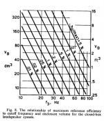
What folks tend to overlook WRT TL/horn design is that they are just odd shaped boxes, which takes 'x' amount of volume [Vb] to get 'y' amount of acoustic efficiency regardless of its shape, so less is always less as shown by Small's nomographs:
GM
GM
Attachments

Yes. They have a similar effective Q, but having a higher Vas and lower Fs, the Pluvia 7 requires a larger line for equivalent results. Which is not to say you will get terrible results in a smaller pipe (it might be, it might not, depends on the pipe), just that they aren't equivalent, and there is by definition more compromise.
+1
FWIW, B0$3 found in testing its Wave Cannon alignment that a 2:1 CR was a good compromise between the pipe's CSA to acoustic axial length ratio.
That said, are any of the MA drivers sufficiently 'stiff' enough to handle any compression loading without excessive over damping of its BW above its upper mass corner and/or in its TL, breakup modes BWs? Published response plots implies they might not be good enough for even < 1:2 CR.
GM
Bearing in mind that efficiency of the low frequencies are unneeded, they will be filtered off. It's the impedance flattening that is desirable in order to make it easier for a 1st order xover. If I can reduce the Z somewhat and reduce it further with a parallel R across the drive unit that may suffice.What folks tend to overlook WRT TL/horn design is that they are just odd shaped boxes, which takes 'x' amount of volume [Vb] to get 'y' amount of acoustic efficiency regardless of its shape, so less is always less as shown by Small's nomographs:
GM
That may, or may not be the case depending on how far you compromise it, what your acoustical crossover frequency and orders are, and how much air-load you are placing on the moving components. If, for e.g., your target 1st order is relatively close to the acoustical rolloff of the driver on that baffle & in that pipe, you may end up with a higher order slope than you intended. Now, if you're fine with that and have confirmed the other aspects are not going to be problematical, you're bobbing. If not -be careful trying to reduce too far.
+1
FWIW, B0$3 found in testing its Wave Cannon alignment that a 2:1 CR was a good compromise between the pipe's CSA to acoustic axial length ratio.
That said, are any of the MA drivers sufficiently 'stiff' enough to handle any compression loading without excessive over damping of its BW above its upper mass corner and/or in its TL, breakup modes BWs? Published response plots implies they might not be good enough for even < 1:2 CR.
Good point about the Wave Cannon. 🙂
Re the MA units, probably not. I kept it down in my big (these things being relative) horns for e.g. In fairness they weren't designed for compression loading; be that as it may though, they're happier with some volume to work in.
Thanks to all who contributed to this thread. Lots of food for thought.
I found this other thread which ended almost 10 years ago to the day which goes into quite a bit of depth on the subject. Including a great pic from Scottmoose.
Closed end TL experiments, impedance flattening
I assume an open ended TL would give similar results to the closed one simulated.
I found this other thread which ended almost 10 years ago to the day which goes into quite a bit of depth on the subject. Including a great pic from Scottmoose.
Closed end TL experiments, impedance flattening
I assume an open ended TL would give similar results to the closed one simulated.
Attachments
Last edited:
Have you considered going active, it would make the speaker design much simpler and more easily controlled?
- Home
- Loudspeakers
- Full Range
- A question about mid-tweeter transmission lines.