Big thumbs up for the Dynaco version. Alot to be said for very simple design. I have never seen that before but would definitely look at that one. What kind of power for P-P 6V6?? 10 to 15 W/ch
On a Dynaco 6v6 pp you get maybe 10w out per channel? That's more than enough for me. Using an el84 SE triodewired, and with 1.5 W class A, it sounds loud enough. Will use the next few days to plan the layout of the aluminum plate. Looking in drawers and shells to see if I have octal sockets..
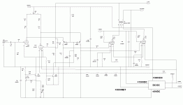
Looks like a bit of a complex thing, hybrid? 8cg7 with 8.4v heaters? Do you have transformers with many different windings for the heaters? Do you make pcb yourself? I stick to the simple, and a 6V6 type Dynaco

You can stick to concepts that make you comfortable, if that's your comfort zone.... I design my own DC-DC converters with dedicated outputs for powering the various functions on the amp. It's what I've been doing for a living for 40+ years - works for me. If you don't like what I do, you have no obligation to go there.
And yes, I lay out my own printed circuit boards, been doing that since 1996, when I figured out Orcad...
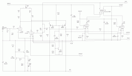
Maybe using a CCS instead of R26/27? The amp is DC coupled, right? That should help keeping the right quiescent current for the 6P1Ps.I finally got my schematic sorted out - here's what I have...
Last edited:
That's way more parts than my personal comfort zone. The DC-DC converter that powers the amp gets inherent line and load regulation from the switching adapter that feeds it - that, and the balance adjust pot I deliberately put in, should be good enough for this implementation of the amp. I have another amp in the works with automatic balance adjust, but that's a whole lot more parts flung into the mix, and way too ambitious for the simpler amplifier I had in mind here.
Your call, of course. I'd say that a cathode ccs just adds one component per output tube, an LM317 CCS will do the job perfectly. No need for complicated cascode ones, here the CCS is blocked for AC.
Not happening - you apparently don't understand what I'm trying to accomplish with this design. And yes, yes, it is most definitely my call as to what I want to do with this design. I'm most certainly not adding any CCS to my output tubes, especially not a noise factory like an LM317.
I only have one 6V6GT based amp : a BELL 2420 from 1964 - I love it :

One of the tiny original output transformers was dead, so I replaced both with a pair of Grundig (Germany) 8K plate-to-plate transformers, which are two times bigger and of a much better quality than the original OPTs.

I added a pair of vents on the metal cover, which had none... Needless to say that it ensures a better cooling of the circuit !

And Top Notch : the controls are lighted !

That said, it is a fairly simple design 2x12WRMS output circuit, with 3x12AX7, 4x6V6GT, 1xEZ81 only, which offers all the functions you would expect from a complete integrated amplifier.
A clever tip used in this amp is to heat in DC the two first 12AX7, by using their filaments as the common (decoupled) cathode resistor of the four 6V6GT, providing the 24V cathode bias required :

Simple and efficient...
T
One of the tiny original output transformers was dead, so I replaced both with a pair of Grundig (Germany) 8K plate-to-plate transformers, which are two times bigger and of a much better quality than the original OPTs.
I added a pair of vents on the metal cover, which had none... Needless to say that it ensures a better cooling of the circuit !
And Top Notch : the controls are lighted !
That said, it is a fairly simple design 2x12WRMS output circuit, with 3x12AX7, 4x6V6GT, 1xEZ81 only, which offers all the functions you would expect from a complete integrated amplifier.
A clever tip used in this amp is to heat in DC the two first 12AX7, by using their filaments as the common (decoupled) cathode resistor of the four 6V6GT, providing the 24V cathode bias required :
Simple and efficient...
T
My design is a little more complex than the average bear, but it addresses blocking distortion, and also removes a few pounds off the chassis in the form of the power transformer.
Found an old Densen amplifier that didn't work anymore. Uses the bottom plate which is made of 2-3 mm aluminium. Probably have to reinforce with a little extra aluminum here and there, because the transformers and chokes weigh many kilos. Was thinking of painting the aluminum plate, maybe red?
I want to use 193j
(200mA/10H) right after the first capacitor in the power supply, then there will be a split of B+, where there will be two capacitors, and a 193C i each rail , and possibly one more capacitor, before the wire from these will go to the left and right channels. Have used this procedure on my Tubelab Simple PP el 84 amplifier, and it sounds absolutely beautiful.
(200mA/10H) right after the first capacitor in the power supply, then there will be a split of B+, where there will be two capacitors, and a 193C i each rail , and possibly one more capacitor, before the wire from these will go to the left and right channels. Have used this procedure on my Tubelab Simple PP el 84 amplifier, and it sounds absolutely beautiful.
Forgot to tell that I will also use a Hammond 370 HX. The voltage will be a bit too high, as I will be using diode rectification, and a drop resistor must be fitted...
- Home
- Amplifiers
- Tubes / Valves
- A Push-Pull DIY amp, type 6V6?