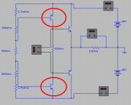
the resistor in zobel is cold, osciloscope did not show anything... it was going nicely all the way to the 100kHz and above nothing.....crazy thing....
i will recheck when i dismount the board.... and than i will let everybody know.... 🙂 thanks for helping Karl... now you know why i am so confused and why i can't figure what is going on.... hehhehehe
anyway - i will everybody know what is happening as soon as i have some new info...
i will recheck when i dismount the board.... and than i will let everybody know.... 🙂 thanks for helping Karl... now you know why i am so confused and why i can't figure what is going on.... hehhehehe
anyway - i will everybody know what is happening as soon as i have some new info...
Hi, Final thought, if you are relying on fixed bias resistor do be careful, it would be so easy to over bias particularly on testing, and a few 10's of mv too much could fry the outputs. Use the 60 watt mains bulb trick untill you get it sorted. I think if it were me I would initially replace the bias network with a pot (say 470ohm) and make sure you can swing the bias current smoothly from zero upward, or more correctly that your voltage at A/B varies smoothly from zero to about 1.5v at which point the outputs should begin to conduct.
Do let us know how you get on.
Karl
Do let us know how you get on.
Karl
thank You Karl - i will.....
as soon as i check everything...i will let everybody know what was and is going on there....
as soon as i check everything...i will let everybody know what was and is going on there....
my friends....
heheheheh
....
IT IS WORKING!!!!
i am stupid idiot.... that is what i am....
i didn't noticed that i forgot to solder base and emitter od the negative driver transistor......
as Carlos said - assembling error.....
it is working like a charm.... - going on a second channel - now, i bit smarter 🙂 heheheheheh
the schematic is original as i intended - with two bjt's and a trimmer in their base....
bahhhh!!!
it was so easy, so beginners error.... can't believe it....... bad!
🙂
anyway the good thing is that it is working properly..... this is good.
it was so easy, so beginners error.... can't believe it....... bad!
🙂
anyway the good thing is that it is working properly..... this is good.
thank You Karl and Carlos too... 🙂)
yes... well. i am happy for sure.....
i onyl have to make few things on the second channel, to bias it properly and than to check how it is sounding...... i am really intererested to hear it.... my first solid state amp (well, not completely but hey, i am learning) and complicated too.... 🙂
hehehhee
You are welcome Sunny.... funny that..you have thanked
Karl and Carlos...so.... Karl and Karl and Carlos and Carlos..or Charles and Charles, hehehe... Karolus and Karolus...all the same.
heheh... if you do that to a neurothical person he will start to make calculations to discover the chances to receive thanks first.
ahahahahah!
Carlos
Karl and Carlos...so.... Karl and Karl and Carlos and Carlos..or Charles and Charles, hehehe... Karolus and Karolus...all the same.
heheh... if you do that to a neurothical person he will start to make calculations to discover the chances to receive thanks first.
ahahahahah!
Carlos
- Status
- Not open for further replies.
- Home
- Amplifiers
- Solid State
- a problem - no bias current
