You get the display from me, it is not an off-the-shelf display, it has been reprogrammed to suit my purpose. If you want to save money, the LED display will be adequate for all volume, balance, mute, and calibrate settings, albeit not nearly as informative as the display. If you want the milliamp readout of your shunt LDRs -- which draw the most current -- you will need the display.
Just to be clear -- where I said "LED display" I meant a simple LED.
Looks pretty nice, so are you going to sell kits ? that unlude display and pre-assembled boards ?
I will sell the pre-assembled boards with all components installed, and the two-line OLED display. All that is required is for the user to connect the boards together -- all the boards have .1" screw terminal strips -- and you mount them as you wish with audio connections and 9~16VDC.
The connections are very simple as shown on the attached drawing. The OLED is not necessary, you can manage the setup by interpreting the simple LED.
While I will sell this first batch as a complete set at a lower price because I want feedback on my entire system, eventually you'll be able to buy boards separately and the LDR board can be used stand-alone with volume and balance pots and no IR, or you can include the other boards for full rotary encoder control and OLED display and IR control.
Attachments

 ???? Please.
I would be very interested in purchasing a full kit with OLED Display. I looked at building my own & purchasing other options, but decided to wait till you finished your design. Have been following the thread for quite some time. Please consider if not even the first round the second. Be happy to send down payment. Thank You
Unfortunately have to suspend my interest in the preamp for now - thanks.
I'm very interested in trying it - it will be my first time use enter your usesing LDR's in a passive preamp (I currently have a DCB1 in my setup).
Any idea of cost yet?
Unfortunately have to suspend my interest in the preamp for now - thanks.
Thank you for the courtesy of the update.
A local business has started the assembly of 30 sets of boards and they have promised delivery late this week or early next week. Control chips will arrive early next week and by the end of next week I should have the boards programmed and tested.
I have a query in to the moderators asking if it's OK to sell this first batch via this thread. If their answer is yes, we'll work it out; if the answer is no, I'll find some other means that doesn't violate diyaudio policies.
The following posts show pictures of the configuration as it is being manufactured now.
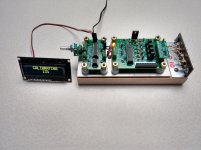
The main change from my previous version is the new configuration of the jumper -- it is now a straight line header so that there is no jumper between the LDRs and the output terminals in 'play' mode. The header running along the side of the board is there to store the jumper board when not calibrating. You won't want to lose that small board.
The jumpers are present only when the calibration board is attached and the LDR board is self-calibrating. This configuration will require the user to unplug the audio cables when calibrating the board but it will be a welcome change to purists who want minimum connections in the signal path. My experience is that once properly calibrated there will be very little reason to recalibrate unless you change the environment significantly, so unplugging cables will not be a hardship.
The photograph shows the calibration board in place and the board is part way through a calibration cycle.
Attachments
Last edited:
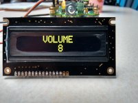
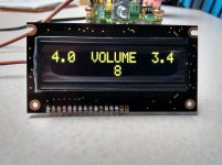
The volume display with, and without, displaying the current flowing through the shunt LDRs.
Notice that the currents are quite different -- this is because the LDRs were not closely matched before installation and therefore are drawing different currents while delivering the same resistance. This is the key advantage of PIC-controlled LDRs.
The volume levels are from 1 to 99; level 8 is fairly low level and therefore considerable current is flowing through the shunt LDRs. At midrange and louder, the display will show "< .1" which means that each LDR is drawing less than one-tenth of a milliamp. Resolution and control at the lowest currents is typically +/- 2 microamps.
Attachments
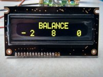
Other display modes:
Balance: with balance intentionally offset slightly. When balanced, both sides will show "0"
Sound Muted: When the device is muted, the display will blink.
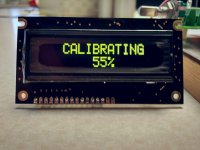
Calibration %: When the jumper is inserted and power applied, the self-calibration cycle begins and the display shows the status of the calibration process in percentage complete. When calibration is 100%, the display will flash "CALIBRATION COMPLETE" and you can power down, remove the jumper, and you're good to go. Calibration typically takes 12~15 minutes.
Balance: with balance intentionally offset slightly. When balanced, both sides will show "0"
Sound Muted: When the device is muted, the display will blink.
Calibration %: When the jumper is inserted and power applied, the self-calibration cycle begins and the display shows the status of the calibration process in percentage complete. When calibration is 100%, the display will flash "CALIBRATION COMPLETE" and you can power down, remove the jumper, and you're good to go. Calibration typically takes 12~15 minutes.
Attachments


Source selector
Hello,
Sorry to go slightly off topic but I am wondering if and Ldr optocoupler could be used to switch sources? Would led-off result in zero signal and near perfect source separation?
-Thanks
Hello,
Sorry to go slightly off topic but I am wondering if and Ldr optocoupler could be used to switch sources? Would led-off result in zero signal and near perfect source separation?
-Thanks
Hello,
Sorry to go slightly off topic but I am wondering if and Ldr optocoupler could be used to switch sources? Would led-off result in zero signal and near perfect source separation?
-Thanks
Actually very much on-topic, it's entirely possible and this is something I'm going to do to complement the volume & balance control.
In order to maintain an across-the-board standardization of input attenuation, it's not just a matter of turning LDRs OFF, but you also need to have a controlled LDR ON resistance. This is necessary so that each input, when turned ON, will have a level consistent with the other inputs.
How often do you have to calibrate the system?
Have you come up with a definite price?
Thanks...
Have you come up with a definite price?
Thanks...
Open a new Thread in swap meet.A local business has started the assembly of 30 sets of boards and they have promised delivery late this week or early next week. Control chips will arrive early next week and by the end of next week I should have the boards programmed and tested.
I have a query in to the moderators asking if it's OK to sell this first batch via this thread. If their answer is yes, we'll work it out; if the answer is no, I'll find some other means that doesn't violate diyaudio policies.
The following posts show pictures of the configuration as it is being manufactured now.
There you can run a group buy or simply sell your product.
Put a link here to direct Members to the buying page.
................ My experience is that once properly calibrated there will be very little reason to recalibrate unless you change the environment significantly,...................
How often do you have to calibrate the system?...................
How often do you have to calibrate the system?
Have you come up with a definite price?
Thanks...
Calibration:
Once calibrated, I have never re-calibrated due to an audible change in the gain curve or balance, which appear to stay rock-steady indefinitely.
The last time I asked him, the other person who has listened much more extensively than I have -- James Hill in Australia, who seems to listen to his system a lot every day -- had never calibrated his sample at all, being satisfied with the calibration as he got it from me, after it transited from the U.S. to Australia. He's a serious audiophile who has A-B'd my board against a number of other LDR systems and high end preamps and I believe he remains satisfied with the original calibration, and he once told me that my board is now his preamp of choice. He's had his sample since last Fall.
The only time I've calibrated a board was during testing or on initial setup when I updated software or hardware or when I switched LDRs around to test the system. I have never re-calibrated because I could tell the system needed it; nothing seems to change enough to be audible. YMMV
So, for me, after I got the calibration firmware working properly it has always been a matter of initial calibration then just listen with no further adjustments, I've never had to re-calibrate due to noticeable problems with image stability or a change in gain pattern.
To be entirely transparent I remind you that this has been a system under development, and because of software updates and revised test boards, each calibration wasn't in place all that long, maybe a maximum of four months at a time until recently. But when I go back to an earlier prototype to listen to because the latest prototype is on my test bench, the old prototype just plays, no calibration required.
So my bottom line is, based on my experience, the answer is "never." But I don't worry about changes that might be measurable with lab equipment -- if I can't hear the change (if there is one) I don't care. These devices are for listening; sort of like vacuum tubes -- they may not measure well but they sound terrific.
Price:
For this buy only, assuming that the diyaudio powers-that-be allow me to sell directly to this group (they haven't decided yet), I'll offer the entire setup of LDR controller, rotary encoder & IR controller, the rotary encoder board with screw terminals and the calibration board (all as you see in the photo above) for something between $220 and $250. This does not include the OLED display which I think can be for a little less than $50 for this group only. The display is not strictly necessary -- you can operate all of the modes through various blink patterns on a simple LED except for the shunt LDR current readout which does require the OLED.
For all of us, if it works out, this is an opportunity -- for you to get the boards discounted, and for me to put a complete set in the hands of a group of people who can give it knowledgeable evaluation and identify shortcomings if such exist and also validate it's quality. Because of this, I would like the entire set of boards to be used as a system and I'm selling them as a complete system. The OLED is optional.
Shipping will be by USPS Priority Mail, about $15 in the U.S. and $26 outside of the U.S., I haven't nailed that down yet, but it cost me $26 for a box to Australia for James Hill's boards.
This is as close as I can get at this point because I still haven't gotten pricing for the PIC chips needed for each set of boards. Hope this helps.
wapo54001 said:Hope this helps.
Yes, it does...thank you.
That OLED display looks so cool that I think I would have to get one of those, too.
I thought I read somewhere that OLEDs have a limited life. Is there a way that the display could be turned off if not changing any of the functions?
I thought I read somewhere that OLEDs have a limited life. Is there a way that the display could be turned off if not changing any of the functions?
The display needs to stay powered up to stay synchronized with the control board, so you can't turn it off without creating uncertainty about how it's going to restore when you turn it back on. The control board does send an initialization routine to the display when the control board is first turned on.
I did some research on that question, and I think your comment is too general from what I understand.
Delving a little deeper, I found that different colored OLEDs deteriorate at different rates, and also with some colors 'burn-in' can be something of a problem. These yellow versions are supposed to be the least affected.
To avoid burn in, after about two minutes of no control input, the display reduces to a simple volume value which moves around the screen much as a computer screen saver does. This is my effort to avoid burn-in; I considered completely blanking the display but I didn't like looking at a blank display so I opted for the screen saver approach..
I think technology will have moved on long before any of these issues present themselves in any meaningful way.
The real issue with OLED displays is that there is an upconverting voltage regulator on the board that can send noise back down the power supply line to disrupt sensitive audio circuits. I've consulted with someone who has studied the issue and he is satisfied that by using separate regulators for the OLED and for the audio control circuitry, this noise does not reach the audio circuits. In my system, each board has its own regulator so there is very good separation of the OLED from the critical LDR control circuit. I cannot detect any issue with noise on the LDR control circuits.
Ah, I'm back online after my house moving efforts - jeez, don't want to do this again for another 10 years!
Have just setup the same system in a completely different room and substantially different sound - plus a few changes to be made with preamp, amps, speakers, diffusers, and for the first time in 2 house moves, bass traps!
As Karl has been mentioned above, there has been no need to re-calibrate this unit at all despite it being given a pretty extensive workout including a transfer to a solid chassis (microphonics, etc), receiving a number of different power supplies, wiring simplifications, I/P & O/P socket changes, minimum volume/mute settings, different sources/loads, etc, etc and about the only thing I haven't done to this long suffering set of boards is to re-calibrate the ldrs - I'm about to do this with the current production control chip upgrade, etc, that does require the re-calibration procedure, so it'll be interesting to finally get around to doing this.
One of the most interesting features of this design is the often neglected balance control - many preamp designs don't include them - sometimes it's handy to re-centre the stereo image/balance a bit, and, surprisingly, sometimes well recorded tracks 'sound better' from a slight off-centre adjustment, particularly with classical music on 'phones
- Status
- Not open for further replies.
- Home
- Source & Line
- Analog Line Level
- A precision LED/LDR-based Attenuator