Has anyone made a PP power stage that interfaced directly to a DAC that already has balanced XLR outputs? Essentially already providing two perfectly phase-inverted copies of the signal right upon D/A conversion. My DAC (Teac UD-503) has balanced XLR outputs.
Can I simply capacitor (or DC) couple these balanced outputs directly to a PP output stage and eliminate (or provide a bypass switch to omit) the phase inversion stage? Is there anything that might get me in trouble by simply doing this? I understand I might need to insert a voltage gain stage on each leg to drive the tubes fully. But that's still only one coupling cap as I could probably DC couple the DAC to the first input stage like any amp.
Since 95% of my music listening is through this TeacDAC I'm thinking it might be worth keeping the signal fully balanced end-to-end rather than using the SE outputs.
Here is my DAC:
UD-503 | TEAC
Last edited:
Sure. Done it more than once. Just take any PP amp with a phase splitting transformer at input, remove the transformer and you're ready to go.
Yes, and it works very well.
But the more simpler the circuit, the more complicated it becomes to manage gain/power/feedback.
I use a double 6V6 PP (trioded, fixed bias) with LL1681 (1:13) as input stage, it sounds very good but a very low Zout source is needed in this case. Not compatible with Teac UD-503 (180 ohms Zout).
6E5P seems to be a good choice..(high gain, high gm, easy to drive)
I built my first balanced amp earlier this year. There is no input transformer needed.
The source is a CD player with XLR + and - outputs (and ground too).
The amp has series resistors from the + and - signals. There is a shunt potentiometer (rheostat) connected across the output of those 2 resistors (volume control, with the wiper connected to one end of the potentiometer). There are grid resistors to ground at that point, and those are connected to grid stopper resistors of the dual triode balanced gain stage. The amplified signals are RC coupled to the push pull output stages.
Works great. Sounds great.
I expect to further develop this idea with changes to that amp, or build another balanced amplifier.
This is what I was thinking too. The Teac DAC is at 188 ohm impedance and it can swing 12 volts. Is that enough to drive EL84 PP to full output? Is all this just an impedance matching effort, or is further amplification needed? I would most likely not need a volume control as I would be basically using the Teac DAC as a pre-amp.
If you get far enough along can you post a schematic here? Also what is the max voltage swing and impedance of your CD player?
If you get far enough along can you post a schematic here? Also what is the max voltage swing and impedance of your CD player?
Careful of your perfect signal, Mother Nature does not like to be defeated 🙂
What about feedback?
You can do what you are suggesting, but if it were my money and time I would pick a design such as an LTP driving EL84 PP that I could just add $2 worth of switch and RCA jacks and use it from either a balanced or unbalanced source, and keep it for years, rather than just until I tired of 1 specific source.
I did mention that I might do a bypass switch on the inverter stage, yes that would make the amp overall more useful. But if one does already have a balanced source why not take advantage of that and offer a balanced input rather than introduce more THD. Since one is using PP topology anyway and the DAC is already serving up two copies of the signal for me on a silver platter. The question is how to best couple it in knowing the impedance and swing of the balanced source. There would be no need for NFB, I dont think, because its only the output pair in play, there would be no need to correct the non-linearities of any previous stages because those stages (gain and inverter) simply dont exist.
Last edited:
Too simplistic. I joked about it already; you should let go of this idea that a balanced signal from the source has some element of perfection about it. If you're not afraid of SS, you can make a driver stage that has great CMRR and low noise (it's called THD+N for a reason), but I think you might assume your perfect CDP also has perfect cables and connectors 🙂
Linear outputstage? Like triodes and $$$$ OPT's? Is that what you really have?
Linear outputstage? Like triodes and $$$$ OPT's? Is that what you really have?
leadbelly, Can you describe your (or anybody else's) perfect playback system (including the perfect room). How about describing the perfect recording venue and equipment? How about describing the perfect instruments and music artists? What is the ideal perfect piece of music? How about describing perfect negative feedback. There is a magazine called "Enjoy the Music". Is that a good idea?
"You should make things as simple as possible, but no simpler" - Albert Einstein
"You should make things as simple as possible, but no simpler" - Albert Einstein
Leadbelly,
I apologize, I misunderstood your statements and direction.
I do sometimes choose to "sail" in less charted waters. There is lots of creativity and originality in this forum.
I apologize, I misunderstood your statements and direction.
I do sometimes choose to "sail" in less charted waters. There is lots of creativity and originality in this forum.
leadbelly,
Can you describe your (or anybody else's) perfect playback system (including the perfect room).
"You should make things as simple as possible, but no simpler" - Albert Einstein
Sure, for audiophiles there is never a perfect in the absolute, only perfect compared to all the other systems you've had your whole life and what you can afford right now. Because we are picky, normal people are happy with a smart speaker and a Pandora account. Perfect are those nights when the music is playing and moving you to another place. But when you're at your table saw cutting wood perfect is an Alexa you can tell "skip song". When you are camping perfect might be a 1984 boom box playing some Count Basie under the stars because you haven't been home for a week. Unfortunately being at Axpona this year, perfect is often defined by six figure price tags. My wife and I listened to many of these and found them unsatisfying compared to some systems under $2000. This field is full of snake oil. Especially, and unfortunately from tube gear builders charging $8,000 for amps whose schematic is not much of a departure from what DIY'ers do here every day!
So this Teac is the best DAC I've ever owned to date, so its todays "perfect". It plays my 6 terrabytes of lossless audio files I have stored on my home network many of which are hi-res SACD rips, double rate DSD rips, and digitized LP's done by folks owning turntables I couldn't afford.
The Teac provides two out of phase copies of the signal already. I'm pretty confident it decoded the data as "perfectly" as can be expected in 2019 and it buffered the analog respectably as a $1,000 unit can.
So I'm sitting here one night thinking why not pair this balanced signal directly to a PP stage to introduce some magic tube THD. Making the measurements a little less perfect (by the numbers) but adding that tube mojo (warmth, harmonics, etc. the stuff audiofools pay $30,000 for) 🙂
So I regret using the word "perfect" I didnt mean in the absolute, nobody knows that. Just that the situation of having a piece of equipment in my rack that is already being a phase inverter, was a "perfect" situation to combine them with a PP stage. Was hoping to see some schematics or what I need to be aware of if it really is as simple as just passive coupling the signal in as though the Teac were my phase inverter.
Windcrest, there are a few 'amp design' aspects that could influence what type of amp could meet your expectations.
Datasheets for the output stage valves can often identify what output power can be achieved for what input signal is applied for a certain class of operation and PP loading impedance and distortion level.
The simplest amp circuit would include no global feedback, and hence you won't achieve very low distortion and very low output impedance, or any suppression of hum from power supply (assuming you used a mains transformer compared to say a 12V plugpack and dc/dc step up type solution).
Operating the output stage in pentode mode gives much higher output power for a given input signal level requirement, but raises distortion and output impedance compared to operating in triode mode.
Operating in just class A gives much lower distortion. Operating at drive levels getting close to grid conduction may cause a rapid increase in distortion.
One example of a simple class A amplifier configuration of output stage (and driver stage) and having as low a distortion as practical before feedback is applied, is the venerable Williamson. It uses moderately large bottle output stage valves (KT66 or 807) in triode mode with 15W output level. It uses 6SN7 for lower distortion than eg 12AU7 or similar.
If you don't use feedback, then the output transformer can be less critical on managing a wide bandwidth, but a requirement for low distortion from the core would still remain.
The STC report for 6BQ5 doesn't provide triode mode in just class A mode, but class AB1 mode may get you 3-4W with 2% THD, depending on whether your balanced output can provide up to 17Vrms grid-grid. You could measure your DAC output for grid-to-grid level with a typical capacitor coupled output to grid leak resistors as used in a PP output stage.
Last edited:
Too simplistic. I joked about it already; you should let go of this idea that a balanced signal from the source has some element of perfection about it. If you're not afraid of SS, you can make a driver stage that has great CMRR and low noise (it's called THD+N for a reason), but I think you might assume your perfect CDP also has perfect cables and connectors 🙂
Linear outputstage? Like triodes and $$$$ OPT's? Is that what you really have?
Thanks, last night I did some experimenting... Conveniently I've already been bread-boarding the Broskie EL84 PP amp that recently popped up in another thread here (the post with "unexpectedly good amp" title to paraphrase). So it wasn't a big deal to try simple passive coupling to the output stage. So I tried coming directly from the balanced source to the output stage, AC coupled to not affect current bias. Its too unstable, Also I think I have a ground hum loop, that might be because I'm using a Eico bench supply and the Teac is still in my stereo rack. I am against doing SS, I have only enough years to live to learn tube amps! I'll have to search around for balanced tube amp schematics to learn more.
This week I will try using the two units of the 6N1P (of the Broskie gain stage) and feed those with the balanced source. Eliminate the phase inverter stage. I think that will stabilize everything for the EL84's and move all the coupling issues to the front where they belong.
I'm also convinced some NFB is needed now. I guess to do that I need to try running two NFB loops per channel. Basically treating the whole circuit as though it were two SE amps, each needing a NFB loop. One for each leg of the phase? So basically both leads of the OPT would be fed back to its appropriate input gain tube phase. I dont know Spice so all of this will have to be done on the bread board.
So basically the whole design question/challenge becomes... "How would someone design a PP tube amp where the phase inverter comes before the first gain stage?" 😕
Last edited:
Not sure of what to say, as the message I am trying to conveigh is not getting across, but that's fine as there are a lot smarter people than me here to help. Again, I suggest an LTP driving the output stage. It gives you the ability to add feedback, and accepts a balanced input. Forget SS if you don't like that, you can resistor load it or pentode CCS load it.
Sorry I missed that, thanks. I will look into LTP input as well. My self-placed restriction is to keep it all balanced right into the PP output stage. A differential amp might be possible as an input stage too (image taken from a Broskie blog post 380):
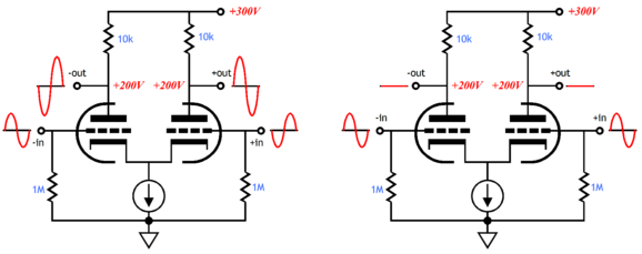

Agreed. Replace cg2 with your inverted input...
Got it! I wasn't thinking of LTP as being a differential amp.
The DIY DAC board that I purchased from K&K Audio installed in my line stage has balanced current output. I/V conversion is accomplished with two pairs of resistors and the signal is fed to the grids of an LTP (6N30s loaded with Lundahl LL1689). My fully balanced mono-blocks do have input transformers (LL1676s) but the XLR connects to the secondary side (CT grid choke) while RCA connects to the primary. Sounds very good and ground loops not an issue. The RCA "inputs" have been recruited to provide galvanically isolated outputs for a subwoofer.
Of note: there are no caps in the signal path. Stages are either direct or transformer coupled. AC signal circulates in closed loops, plate to plate::cathode to cathode. Active current sinks on the cathode side, CCS fed low impedance shunt reg. on the anode side.
Of note: there are no caps in the signal path. Stages are either direct or transformer coupled. AC signal circulates in closed loops, plate to plate::cathode to cathode. Active current sinks on the cathode side, CCS fed low impedance shunt reg. on the anode side.
The DIY DAC board that I purchased from K&K Audio installed in my line stage has balanced current output. I/V conversion is accomplished with two pairs of resistors and the signal is fed to the grids of an LTP (6N30s loaded with Lundahl LL1689). My fully balanced mono-blocks do have input transformers (LL1676s) but the XLR connects to the secondary side (CT grid choke) while RCA connects to the primary. Sounds very good and ground loops not an issue. The RCA "inputs" have been recruited to provide galvanically isolated outputs for a subwoofer.
Of note: there are no caps in the signal path. Stages are either direct or transformer coupled. AC signal circulates in closed loops, plate to plate::cathode to cathode. Active current sinks on the cathode side, CCS fed low impedance shunt reg. on the anode side.
Thanks, being a newbie I dont know why I'm making balanced source handling my first attempt at actual design work (beyond just kit and schematic building). But I'm beginning to understand and six months ago I wouldn't have.
Are the line and monoblock stages on physically separate chassis or is this all one unit? So in the monoblock you are basically bypassing the input transformer (which I assume is normally the phase splitter if used with SE input). That balanced signal is then used as-is for the +/- phase to the PP power stage? The transformer SE input becomes a bonus SE output for subwoofer (albeit stepped down right?). You dont have global negative feed back from OPT to input, but you do have two local feedback loops one in the line stage and another in the power stage? (I have more studying to do on NFB in general let alone how to do it globally on two balanced legs at once).
I'll have to draw a schematic of what I was thinking of doing then gladly have people here rip it to shreds (constructively). Thanks I did pick up a lot from this description. I hope I understood it correctly without a schematic.
- Status
- Not open for further replies.
- Home
- Amplifiers
- Tubes / Valves
- A PP power stage with no phase inversion stage?