An explanation from the beginning
This circuit as very rightly observed SSassen, it has elements from the works of Douglas Self but also John Linsley Hood, mainly in the input stage and in the VAS. All the output and the VI limiter they result from the schemes used in two or three well known P. A. amplifiers. Of course in order to coexist all these together has become a lot work. And primarily because nor the D.Self nor the J.L.H. have occupied with circuits of so much high power. One thing is the biasing of MPSA56 with a Vce of 40V and other thing the biasing of 2N5401 with a Vce of 120V. Moreover and D.Self is building his research on this of J.L.H. and vice-versa. All the designings are built on certain previous, and that the alone important discovery is the silicon. This construction is therefore – as most – a puzzle from already known topologies. She is tried and argued with measurements. Something else also that I wanted to point out, it is that the value that have tests of transient response – with square pulses – she is a lot of superior from the measurements of ÔÇD + Noise or frequency response, because whoever knows it reads oscilograms - that result from these hard test - it also very easily can distinguish or measure indirectly these secondary parameters. This is easily for those who they have knowledge of electronics, of measurements and probably of workbench.
Fotios Anagnostou
Thanks Piercarlo for your interest and for your usefull advises.Piercarlo said:For now, a better quality and more readable picture. It SEEMS a rip of Doug Self.... but it's not, sorry.
Very interesting.
Hi
Piercarlo
Fotios
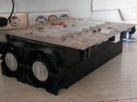
To avoid this, a suggested arangement of the two channels appears in the photo bellow with two PAPST fans 92X92mm.jleaman said:I wonder if this thing puts out as much heat as my ceramic heater ?
Based on these and in the heatsinks SK53 of FISCHER electronics
builded ths project.
Attachments
The Book Of Douglas Self
Our friend Jan Dupont of ACD from Danemark offer a view of this book. Take a look at : http://www.audio-circuit.dk
Our friend Jan Dupont of ACD from Danemark offer a view of this book. Take a look at : http://www.audio-circuit.dk
There is the solder layer from the component side. If it is right in dimensions, can printed directly to transparency. Prefer inkjet transparencies because these not shrinked. If you have any question about to how you can construct PCB at home, inform me.
Attachments
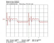
This is an oscilogram indicate the reaction of output inductor in a loading with 8Ù dummy paralleled with a capacitor of 2ìF. Of course it is not so good the damping. Maybe the inductor must be increased from 0,3ìÇ to 0,8ìH but his place inner the zobel - from error this! - looks to absorb the negative jump very well. From luck this! How it is happen this i don't know this moment.
Attachments
Why the low input impedence 18k, this limits it's use to low output impedence solid state pre's, most high end manufatures have started to see the light, and are doing 100k inputs to allow all froms of pre's tubes and passives to be used. 100k is the way to go. Other than that very nice.
Cheers George
Cheers George
The input Z is not 18KÙ as you pointed out. There is a input potentiometer of 50KÙ that is omitted from the plan. Put a resistor of 47KÙ across the input terminals if you try to made this amplifier. If the output of generator or preamp looks directly the cap of 22 ìF it starts to dance Hip-Hop.georgehifi said:Why the low input impedence 18k, this limits it's use to low output impedence solid state pre's, most high end manufatures have started to see the light, and are doing 100k inputs to allow all froms of pre's tubes and passives to be used. 100k is the way to go. Other than that very nice.
Cheers George
Regards
Fotios
Output Inductor Correction
Change the output inductor with a new as follows :
20 turns of Ö=2mm copper wire in two layers from 10 turns each, around a rod of Ö=8mm. A drill bit of 8mm is a good coice. Then the output reaction appears as in the oscilogram quoted in the same frequency of 20KHz. I repeat, this curve measured when connected in the output a dummy resistor of 8Ù in parallel with a capacitor of 2ìF MKT type. Finally, the inductor position inner the zobel looks like better from the usuall position after the zobel.
fotios
Attachments
Re: Yes, thank you Fotios...also thanks to Pinkmouse that have reduced for us
Ripp Off .. of D.Self material??
There is probably no man alive, that has been 'cloned' more often.
If judging by the many amplifiers seen in this forum.
1. You take Self's blameless, for a start
2. You modify / 'improve' to suit your own taste
3. There you are. Post it in this forum.
What not many think of, is that Self used the common way to build amplifiers
as the object for some of his works. Like The Blameless.
In this way it is all an inheritage of common knowledge.
Where Douglas Self has added to this his knowledge & investigations.
And his public papers are surely well worth reading.
Which obviosuly most anybody has done 😀
He is now one of The Most Referenced amplifier designer .. of all times!
------------------------------
Piercarlo 🙂 said:
It SEEMS a rip of Doug Self.... but it's not, sorry.
I believe you, Piercarlo.
Just because it is A Solid State Amplifier,
does not have to say it has anything to do with Douglas Self.
Not anymore than all other amplifiers usingn the same old boring 'op-amp' topology.
Seems people have not much creativity and some new ideas of their own.
We have a few Bright & Interesting exceptions 😎 Of course!
Lineup Audio Regars
SSassen said:This is a blatant rip of a Douglas Self design, even some of the component values on the input stage are the same
destroyer X said:Circuit is interesting...very powerfull...now i am happy.
Piercarlo said:For now, a better quality and more readable picture. It SEEMS a rip of Doug Self.... but it's not, sorry.
Very interesting.
Hi
Piercarlo
Ripp Off .. of D.Self material??
There is probably no man alive, that has been 'cloned' more often.
If judging by the many amplifiers seen in this forum.
1. You take Self's blameless, for a start
2. You modify / 'improve' to suit your own taste
3. There you are. Post it in this forum.
What not many think of, is that Self used the common way to build amplifiers
as the object for some of his works. Like The Blameless.
In this way it is all an inheritage of common knowledge.
Where Douglas Self has added to this his knowledge & investigations.
And his public papers are surely well worth reading.
Which obviosuly most anybody has done 😀
He is now one of The Most Referenced amplifier designer .. of all times!
------------------------------
Piercarlo 🙂 said:
It SEEMS a rip of Doug Self.... but it's not, sorry.
I believe you, Piercarlo.
Just because it is A Solid State Amplifier,
does not have to say it has anything to do with Douglas Self.
Not anymore than all other amplifiers usingn the same old boring 'op-amp' topology.
Seems people have not much creativity and some new ideas of their own.
We have a few Bright & Interesting exceptions 😎 Of course!
Lineup Audio Regars
Another worthless post, you're really making an effort here are you?
Best regards,
Sander Sassen
http://www.hardwareanalysis.com
Best regards,
Sander Sassen
http://www.hardwareanalysis.com
Sander, you sound frustrated.
Stop knocking other peoples designs and focus on making yours better.
Stop knocking other peoples designs and focus on making yours better.
Sander, you sound frustrated.
Really? I'm not the one bringing back old topics with posts that bring nothing new to the table.
Stop knocking other peoples designs and focus on making yours better.
I did, try improving on this:
http://www.hardwareanalysis.com/content/article/1842/extrema-reference-class-a-diy-amplifier/
Best regards,
Sander Sassen
http://www.hardwareanalysis.com
Re: Hi!
Thanks
BTW (i ask the forgiveness of Sander who has the right to express his opinion freely - as we have democracy - it is sufficient to use civilized expressions) i quote below the correct schematic of Dirty Harry, with some propositions for improvents. This amplifier it is intended mainly for P.A. use. I have builded 40 units of it before 8 years and they are working yet without problem (only 3 units returned to me for replacing 2 or 3 output transistors per unit until now) in live stages and clubs mainly to drive big power subwoofers below 150Hz because the new class D or H amplifiers they are unable to reproduce a steep bass such these class AB heavy (30Kg) amplifiers.
Before this i have to clear some things related with D. Self designs.
1) The tripple darlington output stage it is not used by D. Self in any of his projects. This output stage it is borrowed - and not ripp...off - from Peavey CS1200X in which the predrivers changed from MJE340-350 in MJE15032-15033 as well the Vbe multiplier which is well known in many designs.
2) The LTP in input and the VAS has seperate CCS, a scheme used by J.L.H. enough years before the edition of D. Self book. Moreover D. Self does not use seperate CCS in his design. Also the current mirror scheme it is from J.L.H. and not from D. Self.
3) The VI limitter it is borrowed from the application notes of Motorola
4) The VAS with the EF transistor it is the only novelty offered from D. Self and used in my project. In practice proved that its existence or not, it is the same thing. I think that the cascode it is more effective.
Well, where is the rip of D. Self design?
Now the improvements:
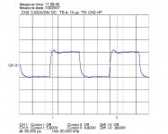
You can obtain a lower rise time than the original of 1,8ìs by changing C9 from 18pF to 10pF and R12 from 330Ù to 100KÙ. You can also remove this network but the Cdom (C13) it is small to suppress the overshoot and thus must increased from 100pF to 120pF. Either of the two changes offers a new lower rise time of 1,4ìs.
P.S. In the schematic does not appears the input termination resistor because in this place used a 50KÙ pot for level control.
Below it is the original curve of the rise time obtained in full output swing with a square of 20KHz in input and a 8Ù load connected in output. From this curve, Glen Kleinsmidth has calculated the slew rate of my amp at 30V/ìs!!! 😀 😀
I will back
Fotios
zeonrider said:@fotios, I, don't see elements PDF.BTW nice amp, real Dirty Harry.
Regards zeoN_Rider
Thanks
BTW (i ask the forgiveness of Sander who has the right to express his opinion freely - as we have democracy - it is sufficient to use civilized expressions) i quote below the correct schematic of Dirty Harry, with some propositions for improvents. This amplifier it is intended mainly for P.A. use. I have builded 40 units of it before 8 years and they are working yet without problem (only 3 units returned to me for replacing 2 or 3 output transistors per unit until now) in live stages and clubs mainly to drive big power subwoofers below 150Hz because the new class D or H amplifiers they are unable to reproduce a steep bass such these class AB heavy (30Kg) amplifiers.
Before this i have to clear some things related with D. Self designs.
1) The tripple darlington output stage it is not used by D. Self in any of his projects. This output stage it is borrowed - and not ripp...off - from Peavey CS1200X in which the predrivers changed from MJE340-350 in MJE15032-15033 as well the Vbe multiplier which is well known in many designs.
2) The LTP in input and the VAS has seperate CCS, a scheme used by J.L.H. enough years before the edition of D. Self book. Moreover D. Self does not use seperate CCS in his design. Also the current mirror scheme it is from J.L.H. and not from D. Self.
3) The VI limitter it is borrowed from the application notes of Motorola
4) The VAS with the EF transistor it is the only novelty offered from D. Self and used in my project. In practice proved that its existence or not, it is the same thing. I think that the cascode it is more effective.
Well, where is the rip of D. Self design?
Now the improvements:
You can obtain a lower rise time than the original of 1,8ìs by changing C9 from 18pF to 10pF and R12 from 330Ù to 100KÙ. You can also remove this network but the Cdom (C13) it is small to suppress the overshoot and thus must increased from 100pF to 120pF. Either of the two changes offers a new lower rise time of 1,4ìs.
An externally hosted image should be here but it was not working when we last tested it.
P.S. In the schematic does not appears the input termination resistor because in this place used a 50KÙ pot for level control.
Below it is the original curve of the rise time obtained in full output swing with a square of 20KHz in input and a 8Ù load connected in output. From this curve, Glen Kleinsmidth has calculated the slew rate of my amp at 30V/ìs!!! 😀 😀
An externally hosted image should be here but it was not working when we last tested it.
I will back
Fotios
- Status
- Not open for further replies.
- Home
- Amplifiers
- Solid State
- A powerFULL amplifier named Dirty Harry