Question. Replacing potentiometer with resistors?
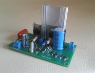
I saw this cool video of @Gabster 2000 testing a cheap Voltage Regulator from Ebay - using Regulators Lm317 & L7809.
I am no engineer, I am a curious creative economist who "can google"... Can you help me set it to 5 V fixed as he does in the video and add fixed resistors? Because small movements in the potentiometer changes the voltage to -+ 2 V !
I want to use it as a cheap way to get better power for my DAC hat for Raspberry Pi. I don't want to kill my DAC.
This is what Gabster is showing... (video at exact timestamp) he replace the potentiometer with resistors according to the video...

1) How do I measure if I need the same resistors?
I am not sure my board is EXACTLY the same, but it looks - to my eyes - exactly like it.
2) His resistors, do not look like resistors to me... I am used to the ones that look like a "worm" with rings on to determine the Ohms... Any input on what to get would be highly appreciated ! I can solder and measure...
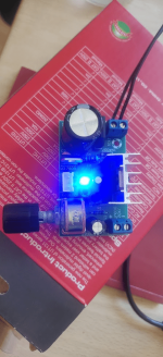
Thanks in advance.. The potentiometer, has 2 x 3 pins and it says B10K on it and W.L on top.
Below are my pics


End..
I saw this cool video of @Gabster 2000 testing a cheap Voltage Regulator from Ebay - using Regulators Lm317 & L7809.
I am no engineer, I am a curious creative economist who "can google"... Can you help me set it to 5 V fixed as he does in the video and add fixed resistors? Because small movements in the potentiometer changes the voltage to -+ 2 V !
I want to use it as a cheap way to get better power for my DAC hat for Raspberry Pi. I don't want to kill my DAC.
This is what Gabster is showing... (video at exact timestamp) he replace the potentiometer with resistors according to the video...
1) How do I measure if I need the same resistors?
I am not sure my board is EXACTLY the same, but it looks - to my eyes - exactly like it.
2) His resistors, do not look like resistors to me... I am used to the ones that look like a "worm" with rings on to determine the Ohms... Any input on what to get would be highly appreciated ! I can solder and measure...
Thanks in advance.. The potentiometer, has 2 x 3 pins and it says B10K on it and W.L on top.
Below are my pics
End..
Attachments
Hello Jungstar,
I don't know this particular board you have shown here. Please attach the link where you bought it that so we can be an useful additional information.
Oftentimes these China PCB boards have slight differences each other, so you are probabily right if you found a different resistor value. What you can try is to use a precision trimmer instead of a knob potentiometer, less accurate.
When you reach the desired voltage turning the screw you'll measure the resistence betweet the trimpot pins and then you can swap with the right resistors.

Thanks @indaco here is the board...
https://www.ebay.com/itm/2632341522...uid=GUr4TDi5RHm&widget_ver=artemis&media=COPY
I tested it out for powering my Raspberry Pi and DAC Hat.... It did not work. I guess I am in doubt about how to set the voltage for the DAC under load...
https://www.ebay.com/itm/2632341522...uid=GUr4TDi5RHm&widget_ver=artemis&media=COPY
I tested it out for powering my Raspberry Pi and DAC Hat.... It did not work. I guess I am in doubt about how to set the voltage for the DAC under load...
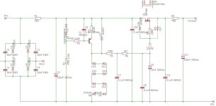
Well, it certainly could have been drawn to better show how it works. One caution with such circuits is overload and short circuit protection. The 317 is normally pretty good in that regard, but here it might not be. That higher voltage output is probably toast if you manage to short circuit it. Test!
I did test it - see the image above... I am just not sure what happens under load.... also, I figured that the DAC Hat and the Raspberry Pi are connected, so when I start the PSU for the Pi , the light on the regulator lights up...

Suppose the 317 type regulator enters it's current limit state. Now the input output differential will be exceeded resulting in failure. That's my guess.
LM317 is quite capable & can provide in excess of 1.5A current. Those cheap kits from China (probably) aren't very reliable & often comes with counterfeit components. Building a linear regulated supply using such IC's is quite easy so i recommend DIY.
I agree with Conrad, I'd be a little cautious on trusting with this board. Then also you have to size correctly the heatsink for your current demand.
Although the schematic is lacking I see a LM7809 for the digital voltmeter and another element (small transistor?) near the output.
Although the schematic is lacking I see a LM7809 for the digital voltmeter and another element (small transistor?) near the output.

1) just adj the potentiometer to get 5V then measure the resistance on each side of the wipers and replace the potentiometer Double check to make sure it is still 5v1) How do I measure if I need the same resistors?
I am not sure my board is EXACTLY the same, but it looks - to my eyes - exactly like it.
2) His resistors, do not look like resistors to me... I am used to the ones that look like a "worm" with rings on to determine the Ohms... Any input on what to get would be highly appreciated ! I can solder and measure...
2) I did not have the exact resistors so I used 2 in series
if using a heavy load and heat sink is getting hot replace with a larger one Do not exceed 1.5A
Hope that Helps 🙂
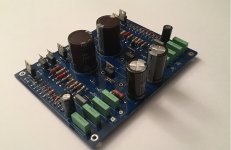
Circuit in post #1. My advice: avoid.
Tricky to judge without knowing what the designer intended or having component values. But for a pre-amp I'd say it's overly complex. Bizarre zener voltage source for the regulator. Regulator output fed back to its input is problematic. Too many capacitors. Just doesn't look expertly designed to me.
Tricky to judge without knowing what the designer intended or having component values. But for a pre-amp I'd say it's overly complex. Bizarre zener voltage source for the regulator. Regulator output fed back to its input is problematic. Too many capacitors. Just doesn't look expertly designed to me.
- Home
- Amplifiers
- Power Supplies
- A particular LM317HV regulator