Hello,
talking to someone I know on the Bay I found out that, among other things, he sells a HV pcb as shown in the schematic,
To my question if it's some sort of Maida regulator he said no, nor a multiplier (until now I hadn't seen a LM317HV regulated by zeners).
He said it was designated by a technician friend of his. I was wondering if there is someone more expert than me who can tell me about the reliability of the circuit, possibly to be used for a preamp. Thank you
Attachments
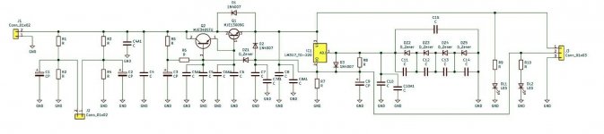
There are no values (just a topology), so it is not technically a design, but it may work ok.
The LM317 is used as a current source to feed a resistor, which acts as a reference voltage for the pass transistors.
What regulated DC voltage do you need? You won't know how well it works unless you simulate or prototype it.
The LM317 is used as a current source to feed a resistor, which acts as a reference voltage for the pass transistors.
What regulated DC voltage do you need? You won't know how well it works unless you simulate or prototype it.
Last edited:
This may be too noisy for a tube phono stage (if so, add extra RC decoupling for the phono),
but it may be ok for a tube line stage.
but it may be ok for a tube line stage.
Yes, it would be a line preamp. The only doubt I have is for that string of zeners, isn't there the risk to have low dynamic regulation and "noise" due to them?
Nothing is perfect, but the Zeners have a constant current, unlike the reference resistor, which is not filtered.
The LM317 will contribute noise to the regulated output, probably more than the Zeners.
The LM317 will contribute noise to the regulated output, probably more than the Zeners.
Ok. At the end I think I'll go to a simpler DN2540+mosfet pass regulator. I tend to avoid complexity, unless the circuit specifically requires it, and taking less space too.
If you live in the UK, good luck finding an LM317HV Regulator at a reasonable price, unless you have an account with RS or Farnell where you'll need to pay the extortionate price for postage. Oh, I have seen this before on ebay. I bought the PCB. It's getting hold of that LM317HV is my problem.Hello,
talking to someone I know on the Bay I found out that, among other things, he sells a HV pcb as shown in the schematic,
To my question if it's some sort of Maida regulator he said no, nor a multiplier (until now I hadn't seen a LM317HV regulated by zeners).
He said it was designated by a technician friend of his. I was wondering if there is someone more expert than me who can tell me about the reliability of the circuit, possibly to be used for a preamp. Thank you
If you live in the UK, good luck finding an LM317HV Regulator at a reasonable price, unless you have an account with RS or Farnell where you'll need to pay the extortionate price for postage. Oh, I have seen this before on ebay. I bought the PCB. It's getting hold of that LM317HV is my problem.
Yes it is so. I have the opposite problem, I used to buy on ebay UK some other rare component here and now I gave up due to customs duties and biblical shipping times.
This is a Maida regulator circuit with Darlington pass transistor. The bottom resistor (in series with R8) is replaced by series connected Zener diodes. If R8 is 220R per LM317 data sheet the zener diodes current is 1.25V/R8 which is 5.68 mA.
Nothing you write home about the circuit.
Art
Nothing you write home about the circuit.
Art
Actually, it's not technically a regulator. It is a pair of emitter followers with the base voltages set by a constant voltages.
There is no regulation mechanism that corrects for output voltage changes.
As output current increases, Vout will fall, and vice versa.
The '317 is used as a constant current source, which will work, but has nothing to do with this being a regulator, which as explained it is not.
Jan
There is no regulation mechanism that corrects for output voltage changes.
As output current increases, Vout will fall, and vice versa.
The '317 is used as a constant current source, which will work, but has nothing to do with this being a regulator, which as explained it is not.
Jan
Yes the two series transistor in the first part of the circuit are configured as LP filters (capacitance multiplier) if I'm not wrong. Instead the second one with the LM317HV wasn't so intuitive for me like this, but what you say has its sense
The man who designed this circuit referred to it as a regulator.
https://www.ti.com/lit/an/snoa648/snoa648.pdf
Art
https://www.ti.com/lit/an/snoa648/snoa648.pdf
Art
Yes. The thing is, it has all the parts to turn it into a full-fledged regulator, if desired.
I understand that some don't want a regulator, for whatever reason, and that's fine of course.
But then don't call it a regulator if it isn't.
I don't want to be pedantic, but we should call a horse a horse IMV.
Jan
I understand that some don't want a regulator, for whatever reason, and that's fine of course.
But then don't call it a regulator if it isn't.
I don't want to be pedantic, but we should call a horse a horse IMV.
Jan
Last edited:
Edit:The man who designed this circuit referred to it as a regulator.
https://www.ti.com/lit/an/snoa648/snoa648.pdf
Art
I need to look at the circuit again; maybe I am seeing it wrong.
Give me some time.
Jan
Last edited:
Sorry guys, the schematic in post 1 is essentially the same as in fig. 2 of the Texas Instr. / Nat Sem
application note of post 14 except for a lot of added components especially in the input.
Output of the LM317 regulator goes to pin 2 of the output socket. I still call a regulator a regulator.
Another output with voltage higher by a value set from DZ1 is provided on pin 1 of this connector.
IC1 LM 317 does not work as a constant current source (post 2 and 12). Jan Didden would call this
a "stupid mistake" ..
People did not notice the topology of a clumsy drawing.
Re the original reliability question - the outputs are not short circuit proof.
Edit : interesting enough I reloaded the page before posting but post 16 did not show up.
Last edited:

I see that the original circuit is indeed a regulator.Edit:
I need to look at the circuit again; maybe I am seeing it wrong.
Give me some time.
Jan
I mistook the '317 as connected as a constant current source, but it really is connected as a regulator, albeit in a somewhat convoluted way.
Apologies for the misleading thrust.
Jan
I did not know what a Maida regulator is, but Michael Maida is the author of this app note (post 14).
Just for sake of information I report the link of Ebay (in italian) with the board:
https://www.ebay.it/itm/373986309941
Towards the end of the listing description, note that the circuit has 2 output voltages which one refers to T1 and the other to IC1.
For the rest I agree with Audiohead, the circuit is essentialy the same of fig.2 of PDF except the add of some more capacitors by the designer (in particular for zeners and IC1). It reminds me also the Finesse circuit somehow.
- Home
- Amplifiers
- Power Supplies
- A particular LM317HV regulator