Hi there Gimpy,
If you are a noob, just like me, i would advice to read Doede's personal website about the dac.
He explains everything, from idea to the final product, it's very well documented with diagrams and parts lists, almost everything you need to understand.
And if you don't understand just ask here and they help you to understand.
DDDAC 1794 NOS DAC - Non Oversampling DAC with PCM1794 - no digital filter - modular design DIY DAC for high resolution audio 192/24 192kHz 24bit
 Paulus
If you are a noob, just like me, i would advice to read Doede's personal website about the dac.
He explains everything, from idea to the final product, it's very well documented with diagrams and parts lists, almost everything you need to understand.
And if you don't understand just ask here and they help you to understand.
DDDAC 1794 NOS DAC - Non Oversampling DAC with PCM1794 - no digital filter - modular design DIY DAC for high resolution audio 192/24 192kHz 24bit
PaulusApologies if this has already been discussed, I have not read all the posts.
I've tried dddac among other things but this part from www.dddac.com/dddac1794_design.html has never been clear to me:
"The datasheet is telling you, that in no digital filter mode, the word clock needs to be 1/4 to 1/8 of Fs.... How on earth to do this without complex logic and or processors? I almost gave up, till I finally started to get an idea why this was! Only to keep the whole clocking system inside the chip locked in so to speak. For this reason the system clock is used, which normally is 4 times BCK (the bit clock of the digital data). A logical thought was to reduce the System Clock (SCK) by 4 and the whole thing must be ok than. And then the final spark.... BCK is actually 1/4 of SCK, so why not connect BCK to the SCK input? This is against ALL LOGIC and seems to be definitively not supported by the datasheet...... BUT ..... it works perfectly 🙂 What a throw, instead of tons of CPU and glue logic stuff, just connect SCK to BCK, haha !!"
just my two cents after a bit of digging
The pcm1794 documentation states that
"The word clock (WDCK) must be operated at 8× or 4× the desired sampling frequency, fS."
In external digital filter mode, since oversampling is supposed to be done externally, 4 or 8 times more samples need to be acquired, so WDCK must be 4 or 8 times faster. By keeping WDCK unchanged, the dac must be fed at high sampling rate else it will be missing data to operate optimally.
This can be seen when looking at the sinewave 10 KHz of www.dddac.com/dddac1794_test_specs.html
-> wide staircases because the 67 current generators after the SDM inside the dac would normally get one extra sample in between. It deteriorates when running at 88200 or 44100.
Regarding BCK/SCK, the documentation states:
"The PCM1794A device has a system clock detection circuit that automatically senses the frequency at which the system clock is operating."
Connecting BCK to SCK is a way to fool the chip because BCK is higher for higher sampling rates.
I also tried an external upsampler:
http://www.xilinx.com/support/docum...el-real-time-upsampling-with-xilinx-fpgas.pdf
to compare with the DAC internal oversampler, but measurement and listening comparisons were remarkably similar in both cases.
The whole point with my DACis to avoid any form of digital filtering as it sound so much more analog and natural.
Just wanted to check with everyone, that if I am using a 4 stack configuration with the old (Red) motherboard, will my DAC be detected successfully on a Windows 10 system? I want to use the latest versions of the Bug Head Player and the new ones only work with Win 10, so want to confirm.
Karticj,
Dac is not detected anywhere. Usb onterface is.
And usb interface does not care about the number of dac bpards you have.
So as long as everything is installed as per Doedes instructions it should be working fine with any number of boards
Sent from my ONE A2003 using Tapatalk
Dac is not detected anywhere. Usb onterface is.
And usb interface does not care about the number of dac bpards you have.
So as long as everything is installed as per Doedes instructions it should be working fine with any number of boards
Sent from my ONE A2003 using Tapatalk
Yes, to be technically correct what I meant to ask is that is the waveio device detected properly in Win 10? Since originally doede shared the drivers till win7, i want to make sure that an upgrade to win 10 will not have any issues. Also, has anyone tried the bug head player?
You can ask Lorien for the latest drivers through his web site. I beleive the last version is working fine with windows 10
Sent from my ONE A2003 using Tapatalk
Sent from my ONE A2003 using Tapatalk
I think he is called Lucian Romega,
and you can reach him here.
ekits@luckit.biz
Or his site:
Luckit | Audiophile grade DIY products
and you can reach him here.
ekits@luckit.biz
Or his site:
Luckit | Audiophile grade DIY products
I think he is called Lucian Romega,
and you can reach him here.
ekits@luckit.biz
Or his site:
Luckit | Audiophile grade DIY products
Thanks much!!
@ Jan: thank you for support! Informations about me are correct!
@ kartick: WaveIO is properly detected on Windows 10. In fact, right now I'm testing a board for someone else and I can post a picture about how can WaveIO is shown in Windows 10 "Device Manager".
For other questions regarding WaveIO please use this thread.
Kind regards,
Lucian
@ kartick: WaveIO is properly detected on Windows 10. In fact, right now I'm testing a board for someone else and I can post a picture about how can WaveIO is shown in Windows 10 "Device Manager".
For other questions regarding WaveIO please use this thread.
Kind regards,
Lucian
Attachments
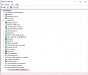
This looks very legit and proper. Im gonna confidently try out windows 10 this weekend and be able to try out the latest release of the bug head player. Has other people really tried this player in a PC setup?


Really awesome Simon ! is the DAC already inside ?
Thanks! Starting to put the DAC inside 😛 many hours work but soooooo worth it
That looks great Simon. Does the network input mean you've added a streamer board? Or are you future proofing?
That looks great Simon. Does the network input mean you've added a streamer board? Or are you future proofing?
Cheers ! Future proofing
- Home
- Source & Line
- Digital Line Level
- A NOS 192/24 DAC with the PCM1794 (and WaveIO USB input)