I measured similarly at the output of the transformer, about 2.35VRMS using an oscilloscope, I don't trust the DMM for those measurements.
Keep it simple Kartick, just exchange one cinch and see what happens. If all is fine BEFORE the cinch and not after, it must be the cinch right?
I measured similarly at the output of the transformer, about 2.35VRMS using an oscilloscope, I don't trust the DMM for those measurements.
Nixie, my DMM apparently does well when getting these readings because at the back of the RCA jacks, I did get an exact reading as I got on the Pos/Neg terminals of the DAC. Just have to solve this bloody mystery of why at the outer ends of the RCA jacks the Vac readings are 0.33. I will test it in a while with an RCA cable plugged in as Bfpca suggested. If the cinches are losing out that much voltage, it is a crime but I think I measured voltage out of another dac i have using the same method on the rca plugs, and i was getting round about that same 0.3-0.4vac. I think it is to do with how the DMM probes dont make proper contacts rather than the cinches going bad on both devices.
OK, Kartick, please sort it out before we spent too much of the thread on this. It becomes clear it has nothing to do with the DDDAC, so much we could clear for now. All the rest is straight forward checking of measurement gear cables, probes whatever. no need for discussion right here. You know how to do that 🙂
OK, Kartick, please sort it out before we spent too much of the thread on this. It becomes clear it has nothing to do with the DDDAC, so much we could clear for now. All the rest is straight forward checking of measurement gear cables, probes whatever. no need for discussion right here. You know how to do that 🙂
Got it DD. There wont be another post about these accessorised aspects.
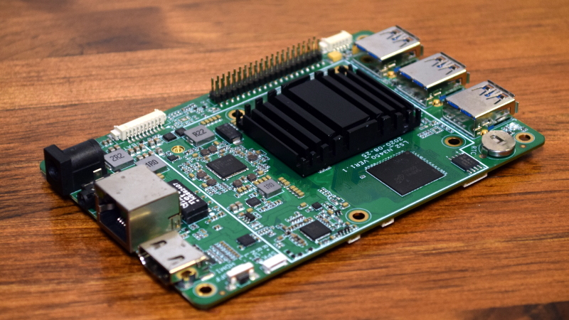
Wrote a small article about which streamer / music server to get for the dac over on the Asynchronous I2S FIFO project thread and figured others would be interested in a much more powerful RPi, but no reaction.
Since Ian's FifoPi re-clocker and Doedes DAC is so connected, I figured I would share the article here as well via a link to the original one.
Enjoy.
A x64 "Raspberry PI"
Since Ian's FifoPi re-clocker and Doedes DAC is so connected, I figured I would share the article here as well via a link to the original one.
Enjoy.
A x64 "Raspberry PI"
Looking at the I/V stage in the latest version 5.1, I noticed that the dac chn. output was inverted (upside down) on the motherboard, which both bothered me and confused me.
So I flipped it and named the dac output to what they are called on the chip and I am simply asking if this is correct as is show in the picture bellow ??

(You are looking at a SE output which is using (going to) custom 1:1 Bifilar "Hi-nickle" or Amorphous core isolation transformer from Intact Audio (Dave Slagle)
which allows the usage of his AVC (Autoformer Volume Control).
So I flipped it and named the dac output to what they are called on the chip and I am simply asking if this is correct as is show in the picture bellow ??
(You are looking at a SE output which is using (going to) custom 1:1 Bifilar "Hi-nickle" or Amorphous core isolation transformer from Intact Audio (Dave Slagle)
which allows the usage of his AVC (Autoformer Volume Control).
Hi oneminde:
not sure I can follow you what is wrong? I checked version 5.1 and older versions and I believe it is all labelled correctly in the technical documentation. I checked older doc versions 3.0 and 4.4 and I could not see a change you are referring to?
Your drawing is kind of correct but in Mono Mode there is no such thing as Left and Right. The datasheet still labels it as L and R, but I choose to use A and B to avoid confusion on stereo vs mono mode.
by the way, what does NEG Left (not used) in your drawing means?
Please let me know what it is you are looking for?
thanks.
Doede
Finally a DDDAC Sowter Post
Finally I made a comprehensive story on the DDDAC Sowter
For everyone who have these (to read about it)
or everyone else who is thinking about it for the future 😎
Link to BLOG post about DDDAC Sowter OPT
Finally I made a comprehensive story on the DDDAC Sowter
For everyone who have these (to read about it)
or everyone else who is thinking about it for the future 😎
Link to BLOG post about DDDAC Sowter OPT
Hello,
Many people cant read properly or dont want to spend time reading for these people:
YES you need 4 boards
YES for correct use better read the manual.
YES they sound very good.
Which one will sound better an eight board DDDAC with caps or a four board one with the Sowter? I am no sure but i would go for the last one because for the first you will also end up spending more money on the supply.
OOH YES, i started with the Sowters right away.
Greetings, Eduard
Hi Doede, the DC capability of the special Sowter transformer is nice of course. But did you consider implementing a trimmer pot across the load resistors to adjust the DC imbalance to zero? This would allow using pretty much any transformer.
Finally I made a comprehensive story on the DDDAC Sowter
For everyone who have these (to read about it)
or everyone else who is thinking about it for the future 😎
Link to BLOG post about DDDAC Sowter OPT
This is great DD, very timely for me as I was anyway looking for a lot of answers in general about DDDAC Sowters and OPTs in general. A very well put together write up from you. Cheers!!
I have a few questions in general, if you or any feels those are worth answering please do, else ignore. These might be due to my dim technical information.
Q1. What is the importance of the input voltage signal in a dac? Most redbook sources have an output of around 2Vrms which is fed into the dac. What if we supply a higher voltage signal to the dac? Does it change anything? Does it drive the dac better?
Q2. Is there a possibility or rather any benefit of using an AES/EBU input in place of a SPIDF input connection? Can we change the spidf connection on the DDDAC to an AES/EBU or perhaps keep both? I understand a converter circuit or a transformer might be required to do this.
I ask this as I have an external clock/upsampler/voltage booster device which can take spidf/aes inputs from a transport/cd player and can output a spidf or an aes output which carries a 5V output. Basis the answer to Q1 above, it will let me know if supplying this 5V signal to DDDAC will help or be a pointless affair.
Hi Doede, the DC capability of the special Sowter transformer is nice of course. But did you consider implementing a trimmer pot across the load resistors to adjust the DC imbalance to zero? This would allow using pretty much any transformer.
That is super interesting and will open up a lot of possibilities to be tried with the DDDAC.
Hello,
Almost sure that if it would have been this simple Doede would have used it
Of course the transformer will also block a lot of things that you dont want to end up in the next part of your chain.
One more big plus it will have eternal life and eventually they will go up in price when they will end up at your grandchildren just like a Gibson Les Paul.
Greetings, Eduard
P.s They are delivered corona proof
Last edited:
Nothing is or was wrong with your schematic and you express design freedom, which is fine. All that I wanted for myself was to "correct" the pin out and line name to be a match such that I didn't have to think which belonged to what 🙂Hi oneminde:
not sure I can follow you what is wrong? I checked version 5.1 and older versions and I believe it is all labelled correctly in the technical documentation. I checked older doc versions 3.0 and 4.4 and I could not see a change you are referring to?
Your drawing is kind of correct but in Mono Mode there is no such thing as Left and Right. The datasheet still labels it as L and R, but I choose to use A and B to avoid confusion on stereo vs mono mode.
by the way, what does NEG Left (not used) in your drawing means?
Please let me know what it is you are looking for?
thanks.
Doede
And I understand that in the configuration used in this dac, L & R does not make sense, but I refer to my first line of text.
Okay, NEG left (not used) refer to in part: The negative portion of the output which is only useful for balanced output and since this is single ended it become not in use OR not connected... (not connected) becomes redundant since there is an X on the line symbolizing not in use or not connected ... LOL
Then we have the Left, well this is simply a reference to left output of the DAC.
So I got my answer regarding the pmc1794 output pin connection and inverted connection which is correct.
Hi Doede, the DC capability of the special Sowter transformer is nice of course. But did you consider implementing a trimmer pot across the load resistors to adjust the DC imbalance to zero? This would allow using pretty much any transformer.
yes, but but doing so, also the signal balance will change. probably all not audible, but hey, I had the Sowters already and everyone can implement a solution like that as tweak of course. Straight forward indeed.
This is great DD, very timely for me as I was anyway looking for a lot of answers in general about DDDAC Sowters and OPTs in general. A very well put together write up from you. Cheers!!
I have a few questions in general, if you or any feels those are worth answering please do, else ignore. These might be due to my dim technical information.
Q1. What is the importance of the input voltage signal in a dac? Most redbook sources have an output of around 2Vrms which is fed into the dac. What if we supply a higher voltage signal to the dac? Does it change anything? Does it drive the dac better?
Q2. Is there a possibility or rather any benefit of using an AES/EBU input in place of a SPIDF input connection? Can we change the spidf connection on the DDDAC to an AES/EBU or perhaps keep both? I understand a converter circuit or a transformer might be required to do this.
I ask this as I have an external clock/upsampler/voltage booster device which can take spidf/aes inputs from a transport/cd player and can output a spidf or an aes output which carries a 5V output. Basis the answer to Q1 above, it will let me know if supplying this 5V signal to DDDAC will help or be a pointless affair.
thanks for the flowers Kartick!
Q1: Not sure about your question: let me try to explain The digital (red book or any other 16 bit format) has a resolution scale from -96,3dB to 0dB. we call that dBFS (from Full Scale). It is totally up to the concept of the DAC what output voltage is created by that. The DDDAC does 1.2V rms (for design reasons - see my website) many other DACs or CDs make for compliancy 2V rms out of it, as they almost ALL have opamp circuits after the DAC chip. So in fact CD players and DACs are mostly a DAC itself (chip or discrete) and an amplifier stage making any voltage out the -96 till 0 dBFS scale.... So you cannot send a higher voltage signal to a DAC. it is always max 0dBFS etc
Q2: I see no advantage. The signal is exactly the same. The AES is just a balanced signal with high voltage for use in studios and live concerts. There you have lots of signal noise and long cables to account for. For home use I see no issue sticking at spdif
OK, now I understand Q1 - still let the answer there.... so as per Q2 no need for higher voltage in spdif
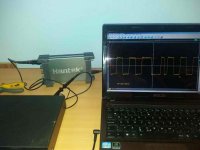
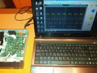
@kartick, WM8804 will tolerate 5VP-P, I tried it with 4.5VP-P and it worked. I am currently using a modified DVD player with a 2.24V P-P SPDIF signal at the output and it works quite normally. The stock output on that DVD player is 0.63V P-P. By standard, SPDIF signal is 0.5-0.6V P-P, and the minimum is 0.2V P-P.
@Doede @Nixie, basically in simple terms, I want to know if I would have been able to get a signal measuring 5V via AES/EBU to the DDDAC in place of whatever say a 2.something volts via SPIDF, would I have gotten a more robust drive on the dac and hence a better output from the dac?
Also, DD, i guess the balanced vs single ended debate is age old so wont go there but just a casual observation, using spidf out vs aes out to my reclocker device, the sound via aes is much more robust, smooth and not as lean as when using spidf. But this is just my subjective observation on my system.
Also, DD, i guess the balanced vs single ended debate is age old so wont go there but just a casual observation, using spidf out vs aes out to my reclocker device, the sound via aes is much more robust, smooth and not as lean as when using spidf. But this is just my subjective observation on my system.
I mostly don't listen to SPDIF now, using just the USB port on DDDAC. When I modified the DVD player SPDIF output by avoiding the lines on the PCB and the original output buffer and taking the SPDIF signal directly from the chip in the DVD player, I got a much better (more correct signal) and better sound. I don't believe that the improvement was due to a higher signal level, but due to a better signal shape. This is Pioneer DV300. I have also modified several pieces of DV600, DV610, DV393 with a good result so far. I got the idea from here. I just happened to have a DV610 that wasn’t used much. I later got a DV300.
goldmundizator
goldmundizator
Attachments

Last edited:
- Home
- Source & Line
- Digital Line Level
- A NOS 192/24 DAC with the PCM1794 (and WaveIO USB input)