Hi Enrico,
Could you give me step by step instructions? Don't be afraid to state the obvious, I'm not very technical.
Jan
Hi Jan,
The target of the CCS circuit is to bias the pin 20 of each DAC chip at 0,4 mA and 2,4V.
To create a stable circuit we are using a Jfet biased through a resistor at the above 0,4mA. If I don't remember wrong you get from carlsor a set of Jfet with a set of resistors already calculated. What you need to add by yourself is the trimmer.
Anyway below are the simple steps to take to setup the CCS:
1 - You need a stable measured 2,4 V source. Positive go to the pin 20 point while Negative go to the GND
2 - You should know the value of your fix resistor. Even if you are using the susumu 1% given by carlors I suggest you to measure it with a multimeter and write down.
3 - As I said your target is to bias the circuit at 0,4 mA. So, as per Ohm law V = R X I your target is to read the V across the fix resistor adjusting the trimmer until you can read the value (in V) that will tell you that the circuit is biased at 0,4 mA. For example in my CCS circuit I use the 2SK246Y and I need a fix resistor of 2000 ohm and a trimmer of 500 ohm. Because I know the value of the fix resistor (2000 ohm) I know also that my target is to read 0,8 V across the fix resistor (V = 2000 OHM X 0,0004 A = 0,8 V). You should recalculate the formula using your R values that will give you your target in V for each circuit.
4 - Last suggestion, keep the circuit powered for at least 1/2 hour. Time to time re-check the V value and in case readjust the trimmer.
When the board is adjusted you are done. No more adjustment are required.
Sorry for the long (and maybe obvious) post and I really hope this can help you.
Regards,
Enrico
I used batteries and a voltmeter on its millamps setting to set my ccs boards.
I chose a pair of AA batteries to give 2.4v, connected pos of the battery to + on the meter, neg on the meter to the + of the ccs, then gnd of the ccs to - of the battery and checked for 400uA (0.4mA)
On my cheap meter, I needed to swap the pos wire to a different hole to measure millamps.
If you're using a meter like this, I don't think getting the voltage correct @ 2.4v for your test rig is critical as you're setting the ccs to a specific current which it should pull over a range of voltages.
RE😀c blocking cap on amp
Hi
I need some advice with regards to the necessity to have either caps or transformer as output into my own system.
It is a newly build dac, running for a week or more and I like it very much. I have used Mundorf Supreme 2.2mfd as output caps into RCA input of my hybrid amp.I was thinking from day one to make full use of balanced configuration advantages and isolation benefits of transformer output.
However reading all the posts it seems that if one could get away with it, no cap or transformer is best?
My amp has a 6.8mfd cap in line before an EEC83 valve(after a discreet resister volume control) and then a 1 mfd between the valve output stage and the mosfets. It is a single ended design.
What do you guys say; Am i safe to go direct? and if so, do I use the pos and neg, rather than pos and earth to rca's input
Thanks
Stefan
ps. seems stupid to fuss about 2.2mfd cap if the amp has a 6.8mfd cap in line 🙂
measure between pos and neg of each channel just to be sure. If you have well matched i/v resistors and everything is working nicely, you should can see a very small dc offset between them. Like only a few millivolts.Hi
I need some advice with regards to the necessity to have either caps or transformer as output into my own system.
If you're satisfied that you only have a very small dc offset and also that your amp would take care of that offset even if it was a lot larger, then I would consider it safe to run pos to rca centre and neg to rca outer with no caps or transformers.
Stefan,
It seems that your amp uses coupling capacitors. So DC will probably (disclaimer talk; always check if you have DC on the output to the speakers!) not pass any DC to the loudspeakers. It can happen that a small DC offset will be superimposed onto the bias setting of the tubes, if this is in the range of some miliamps this will never be a problem.
Regards,
update on my chassis
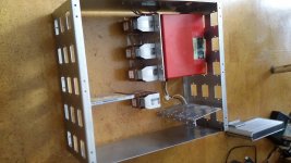
Hello to all the dddac fans,
i did finish my 2 side panels for my dac mainframe. The rectangular holes will be "" covered "" on the inside with a perforated piece of metal or with a piece of metal having an iec input, bnc connector or whatever.
the two panels will be connected by 3 stainless steel 4 mm bars which will be laser cut and will be mounted with the 12 pairs of 5 mm holes.
these bars will have welded nuts each 60 mm to "" receive "" several panels that will support the different parts. The chokes will be mounted using a panel that will be attached to one of the bottom panels. First i wanted to use 3 but now i will go for 4 chokes.
probably there will be a shielding between the chokes and the right side of the chassis.
maybe the chokes will be monted on the area above the power transformer. The 3 bars close to the cover will be identical to the ones on the bottom so can also be used to attach panels with whatever part.
the mainboard will be in the area where the cd is and will be mounted vertically with short leads to the power supply.
the sowter output transformer will probably be in the upper right side part.
the two panels connecting the 2 side panels are just made to show the actual seize of the frame.
the back and the frontpanel can be dismounted with 3 bolts on the left and right side. If there will be switching, leds or something else they will be mounted on a supporting panel right behind the big panel.
any suggestions are welcome because i will be waiting for the new boards.
greetings, eduard
Attachments
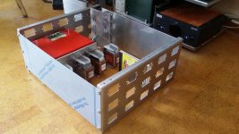
choke connection
Hello again,
My german supplier of the Lundahl chokes ( who seems to have a big stock because yjey did arrive within a week) did tell me to follow the instruction in the Lundahl pdf files. If you connect the 2 colis in the wrong way in series you end up with just a piece of wire!!!
By the way he is also selling an LL2733 which has a 1.25 A rating instead of the usual 1,7 a. On his website he also mentions that the lower the ac voltage across the chokes terminal the higher current it can deliver. Here we use low voltage transformer so current rating will be a lot bigger.
The 1,25 A model ( just the same colis but smaller airgap so less current but higher inductance) will give you 36% more inductance so 544mH with windings in series. Both models have the same price ( just below 100 euro )
Now i can do some test to see what transformer i need for the shunt power supply that i am going to use for the wave IO circuit.
Will post again after the new boards arrive. The present boards with all these added boards look to '' messy '' to me.
Greetings, Eduard
Hello to all the dddac fans,
i did finish my 2 side panels for my dac mainframe. The rectangular holes will be "" covered "" on the inside with a perforated piece of metal or with a piece of metal having an iec input, bnc connector or whatever.
the two panels will be connected by 3 stainless steel 4 mm bars which will be laser cut and will be mounted with the 12 pairs of 5 mm holes.
these bars will have welded nuts each 60 mm to "" receive "" several panels that will support the different parts. The chokes will be mounted using a panel that will be attached to one of the bottom panels. First i wanted to use 3 but now i will go for 4 chokes.
probably there will be a shielding between the chokes and the right side of the chassis.
maybe the chokes will be monted on the area above the power transformer. The 3 bars close to the cover will be identical to the ones on the bottom so can also be used to attach panels with whatever part.
the mainboard will be in the area where the cd is and will be mounted vertically with short leads to the power supply.
the sowter output transformer will probably be in the upper right side part.
the two panels connecting the 2 side panels are just made to show the actual seize of the frame.
the back and the frontpanel can be dismounted with 3 bolts on the left and right side. If there will be switching, leds or something else they will be mounted on a supporting panel right behind the big panel.
any suggestions are welcome because i will be waiting for the new boards.
greetings, eduard
Looks pro, Eduard!!!
Edward,
Very nice Job there. Wish I have that sort of skills!
My power supply is a mess! Recently did a tweak on Choke with digital line. Rather RC, I replaced the equivalent Resistance with Chokes for the appropriate step down DC-voltage suitable within digital Shunts. To my pleasant surprise of better liquidity and texture in timbre. Loving it.
Was going to implement dual ps, each for digital and analog separately, but the risk is too high should either line incidentally not powering?!? The DAC chip might be fired! 😀
Sent from my iPhone using Tapatalk
Very nice Job there. Wish I have that sort of skills!
My power supply is a mess! Recently did a tweak on Choke with digital line. Rather RC, I replaced the equivalent Resistance with Chokes for the appropriate step down DC-voltage suitable within digital Shunts. To my pleasant surprise of better liquidity and texture in timbre. Loving it.
Was going to implement dual ps, each for digital and analog separately, but the risk is too high should either line incidentally not powering?!? The DAC chip might be fired! 😀
An externally hosted image should be here but it was not working when we last tested it.
Sent from my iPhone using Tapatalk
Hi Chanh,
to be honest I did not try this (use dac with ONLY analog OR digital supply) but on the other hand, I cannot see any reason why the chip would fry...
to be honest I did not try this (use dac with ONLY analog OR digital supply) but on the other hand, I cannot see any reason why the chip would fry...
Hi Chanh,
to be honest I did not try this (use dac with ONLY analog OR digital supply) but on the other hand, I cannot see any reason why the chip would fry...
Hi Doede,
Many thanks for your response!
Can I please get it right prior the trail? If I understand you correctly, when power the digital and analog, each with a sperately isolated line, it is safe to have one side (digital or analog) powering while the other is unpowered? In other word, DAC chip will be ok in the event of no electrical power at the digital while analog still powered and vice versus?
I am concerning in the rare event, should either powerline went blackout could damage dac-chip. Hope I make some sense here?
Up on your confirmation, I will conduct this experiment and reporting back. 🙂
Cheers,
Chanh
That's Excellent! Deeply appreciated Doede!let me do this first with my lab dac. not spoil your 11 Tower 😉
Chanh
let me do this first with my lab dac. not spoil your 11 Tower 😉
Hi Chan, nothing has fried on my souped up one boarder over several months but Doedes generous offer is definitely worthwhile insurance group your 11 boarder
David
Hi David,Hi Chan, nothing has fried on my souped up one boarder over several months but Doedes generous offer is definitely worthwhile insurance group your 11 boarder
David
Was you going to be in Perth Australia this year? My invitation is still there for your to audition this amazing DDDAC setup!
I think it is all going well when dual isolated ps are running. Have you had an instance where one of them is blackout? Did it do any permanent damage? This is where area of concerns, what if?
Cheers,
Chanh
- Home
- Source & Line
- Digital Line Level
- A NOS 192/24 DAC with the PCM1794 (and WaveIO USB input)